ISSN ONLINE(2319-8753)PRINT(2347-6710)
ISSN ONLINE(2319-8753)PRINT(2347-6710)
| K.Shamili and P.Golda Jeyasheeli Department of Computer Science and Engineering, Mepco Schlenk Engineering College , Sivakasi, India. |
| Related article at Pubmed, Scholar Google |
Visit for more related articles at International Journal of Innovative Research in Science, Engineering and Technology
Cache memory plays an important role in computer Architecture. The cache memory is the smallest and fastest memory, which reduces the average access to the storage device i.e. the RAID device. The existing cache replacement algorithms work effectively in fault free mode, but with poor performance. When one disk in the disk array fails, the request to the faulty disk is directed to the other non-faulty disks in the RAID disk to reconstruct the lost data. This increases the number of requests to the non-faulty disk. This decreases the performance and reliability of the system. To improve the performance, Victim Disk First (VDF) cache replacement algorithm is used. This algorithm retains the blocks of faulty disk in the cache.ie the blocks of faulty disk are not selected for replacement. This reduces requests to the other non-faulty disk. The VDF-LRU and VDF-LFU cache replacement algorithms are employed to replace the blocks of the non-faulty disks when the cache is full. VDF-LRU efficiently improves the performance by not selecting the blocks that are faulty.
Keywords |
| VDF, VDF-LRU, RAID, CACHE MEMORY, DISK ARRAY. |
INTRODUCTION |
| TO reduce the number of requests to the lowlevel storage device, such as disk arrays, a cache[2][3][11] is widely used and many cache algorithms exist to reduce the long disk latencies. These cache algorithms work well for disk arrays under normal fault-free mode. However, when one disk in a disk array fails, the redundant arrays of independent disk (RAID)[9] may still work under the faulty scenario. The cost of a miss to faulty disks might be high compared to the cost of a miss to other non-faulty disks. Existing cache replacement algorithms cannot capture this difference because they treat the underlying (faulty or non-faulty) disks in an array the same. |
SYS TEM DESIGN |
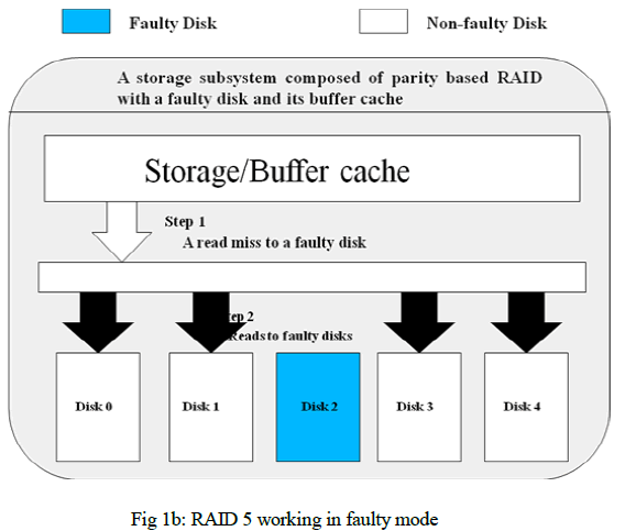
| We take an example as shown in Fig. 1, which illustrates two different cache miss situations in a storage subsystem composed of RAID level 5 which is paritybased with one faulty disk. As shown in Fig. 1a, the missed data resides in the faulty disk. The RAID controller accesses the non-faulty disks to fetch all data and parity in the same stripe to regenerate the lost data. Therefore, to service one cache miss, several read requests are needed depending on the RAID organization. However, if the missed data is in a non-faulty disk as shown in Fig. 1b, only one read request to the corresponding non-faulty disk is generated. |
| Therefore, in parity-based disk arrays under faulty conditions, a miss to faulty disks is more expensive than a miss to other non-faulty disks. Based on this observation, a new cache replacement strategy, named Victim (or faulty) Disk(s) First cache (VDF), to improve the performance and reconstruction duration. The basic idea is to treat the faulty disk more favorably. |
| VDF retains the blocks of the faulty disk in cache. When one disk in the disk array fails, the data of the failed disk is retained in the cache memory. When the cache is full, cache replacement algorithm VDF-LRU is applied to the blocks of the faulty disk and the faulty disk blocks are not chosen for replacement. By retaining the blocks of the faulty disk in cache, the number of requests to the other non-faulty disk is reduced which in turn improve the performance and speed up the reconstruction of the lost data. |
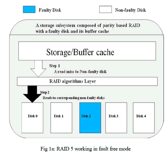 |
| Fig 1a shows the working of the RAID 5. DISK0, DISK2, DISK3 and DISK4 are the non-faulty disk and DISK1 is a faulty disk. The RAID controller accesses the surviving disks to fetch all data and parity in the same stripe to regenerate the lost data. Therefore, to service one cache miss, several read requests are needed depending on the RAID organization. Fig 1b shows the working of RAID 5 in faulty mode. The RAID controller accesses the surviving disks to fetch all data and parity in the same stripe to regenerate the lost data. Therefore, to service one cache miss, several read requests are needed depending on the RAID organization. |
| Furthermore, considering the critical cases in disk arrays tolerating two or more concurrent failures, such as RAID-6, with the increased number of faulty disks, the misses of requests to faulty disks grow accordingly. Thus, the disk arrays would suffer from much more additional requests than that under the case of single disk failure. As a result, the reliability and the performance problems would be more significant. Therefore, in parity-based disk arrays under faulty conditions, a miss to faulty disks is much more expensive than a miss to other non-faulty disks. |
| The three contributions are |
| 1. VDF |
| 2. VDF-LRU |
| 3. VDF-LFU |
| A. V DF |
| Victim Disk First |
| The existing cache algorithms treat the blocks of faulty and non-faulty disks in the same manner so the cost of access to the faulty disk is much higher than the blocks of non-faulty disks, which is because of the more requests directed to the non-faulty disks due to the access of the faulty disk. VDF [8][13] cache is employed which aims in Obtaining the reliability and to speed up the reconstruction duration. Once a miss occurs, typically a block should be evicted from cache, and the missed block would be loaded to the free space. General replacement algorithms evict the block with the smallest access |
 |
| Probability (pi) to reduce the total access probability of the remaining blocks out of buffer cache. |
| VDF evict the block by considering the miss penalty (Mpi ) along with the access probability of the block. When the block resides in cache its Mpi is, |
| Mpi = 0 |
| When the block is evicted from the cache its miss penalty depends on the location of the block i.e. either in faulty (or) non-faulty disks. The eviction of the block should be based on |
| Pi*Mpi |
| The block with the minimum access probability and miss penalty should be chosen for replacement while applying the cache replacement algorithms. |
| B. VDF-LRU |
| The cache replacement algorithm applied along with the VDF is VDF-LRU. The cache replacement algorithm LRU replaces the blocks of the cache memory when chosen for replacement. A counter is maintained in each blocks of the cache. The counter is incremented whenever the block is accessed. The block with the low counter value is replaced with the newly requested block. The VDF-LRU[15] does not choose the blocks of the faulty disk. The blocks of the faulty disk will be maintained in the cache itself which reduces the miss penalty of the faulty disk and reduces the number of requests directed to the faulty disk which is caused by accessing the faulty disk. |
| C. VDF-LFU |
| The cache replacement algorithm applied along with the VDF is VDF-LFU. The cache replacement algorithm LFU replaces the blocks of the cache memory when chosen for replacement. A counter is maintained in each blocks of the cache. The counter is incremented whenever the block is accessed. The block with the low counter value is replaced with the newly requested block. |
| The VDF-LFU does not choose the blocks of the faulty disk. The blocks of the faulty disk will be maintained in the cache itself which reduces the miss penalty of the faulty disk and reduces the number of requests directed to the faulty disk which is caused by accessing the faulty disk. |
IM PLEMENTATION |
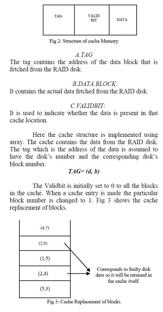
| The cache memory is the smallest memory. In this project the cache contain the data from the RAID disk. The cache memory is divided into blocks. Fig 2 shows the structure of cache Memory. The structure contains the Validbit, tag and data. |
 |
 |
| 3)SIMULATION OF RAID DISK |
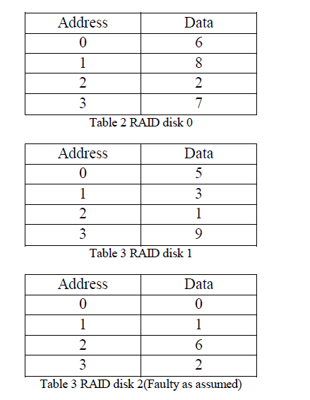
| The RAID level 5 disk is simulated to store the data. The RAID level 5 is assumed to have both faulty and non-faulty disk. The RAID disk is simulated using array structure. The Raid is simulated to have 5 disks. The Table 2, 3, 4 represents the data of different disk in RAID level 5. |
 |
| 4)VDF-LRU |
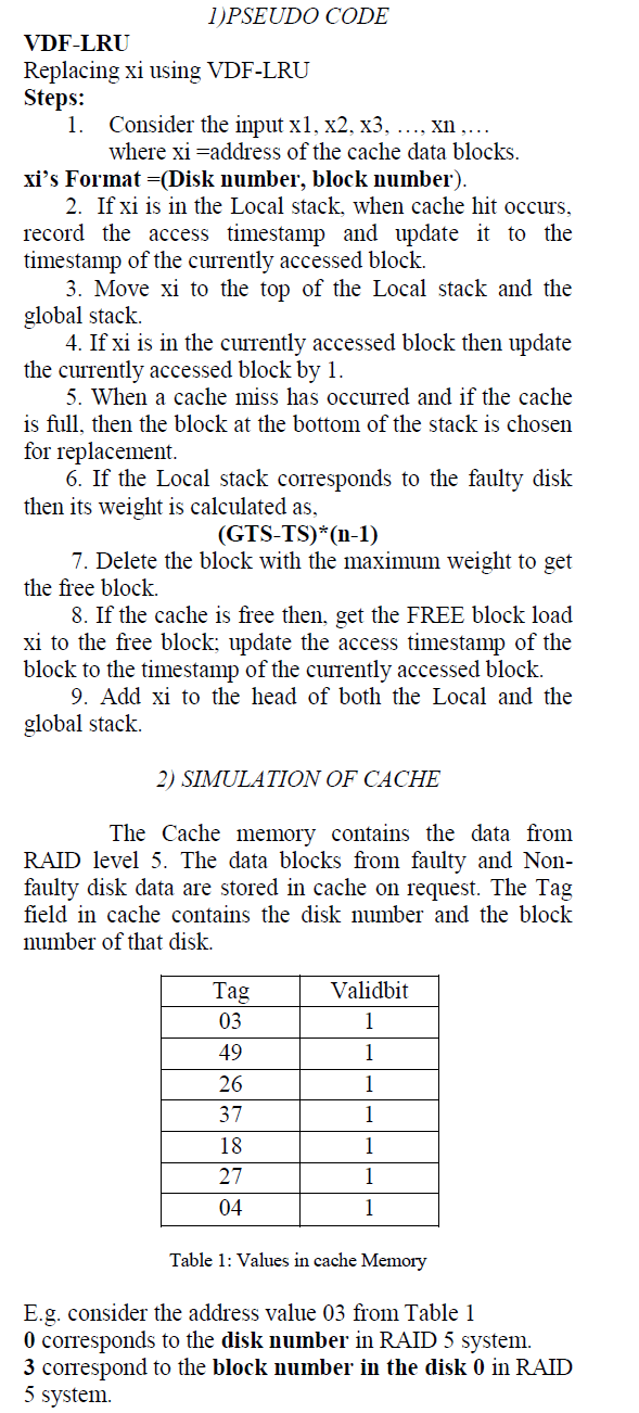
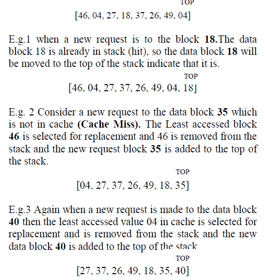
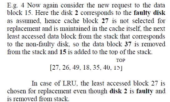
| The VDF-LRU cache replacement algorithm is applied to replace the blocks of the non-faulty disk when cache memory is full. The VDF-LRU uses the stack structure when applying the replacement algorithm. The VDF-LRU takes Tag value i.e. the disk number and block number as input and replaces the block at the bottom of the stack if it does not correspond to the faulty disk. |
| Stack containing the address of data block. Here the disk 2 is assumed to be faulty .So while replacing, disk 2 data block is not chosen for replacement. When a new request is made for the data block already in cache, it is moved to the top of the stack. |
 |
 |
PERFORMANCE EVALUATION |
| The performance analysis of LRU and VDFLRU is compared. The LRU replaces the block at the both of stack considering the faulty and non-faulty data blocks in the same manner. The VDF-LRU treats the blocks of faulty disk more favorable and the faulty disk blocks are retained in cache memory itself. |
| A.LRU |
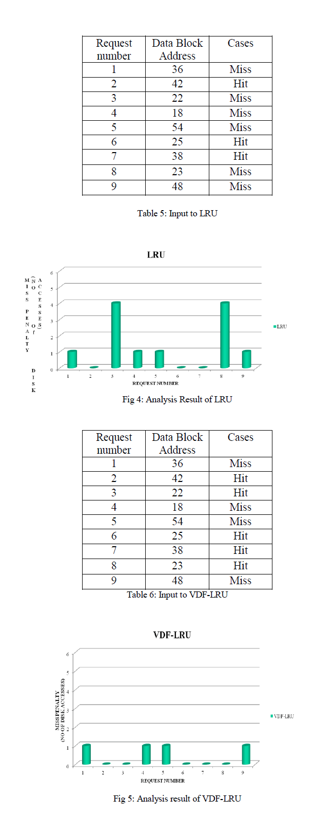
| LRU replacing the blocks of the data block with the minimum access values considering the faulty and non-faulty disk in the same manner and hence when a faulty disk is requested all the other non-faulty disks are accessed. Hence the miss penalty of accessing the faulty disk is higher. Consider the table 4 as an Input to LRU. Fig 4 shows the Miss penalty of accessing the blocks to the cache. Miss penalty is the number of disk accesses made. The Miss Penalty of Cache Hit is “0”. In case of Cache Miss, if it corresponds to faulty disk, its Miss Penalty depends on the number of disk (in this project it is 5). If it corresponds to Non-faulty disk, the Miss penalty is 1. |
| B.VDF –LRU |
| VDF-LRU retains the blocks of faulty disk in cache memory. Hence the cost of access to the faulty disk is reduced. Consider the input in Table 5. Figure 5 shows the Miss Penalty of accessing the blocks in the cache. |
| C.COMPARING THE PERFORMANCE |
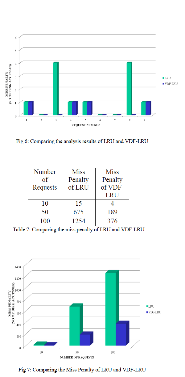
| Comparing the Miss penalty i.e. the number of request of the LRU and VDF-LRU. Figure 6 shows the performance of VDF-LRU is better compared to LRU. Since LRU replaces the recently accessed data irrespective of faulty and non-faulty blocks. |
| Table 6 shows the compared results of Miss Penalty (i.e. number of disk access) with 10 requests, 50 requests and 100 requests using cache replacement algorithms namely LRU and VDF-LRU. Fig 7 shows the graphical representation of the comparison. |
 |
 |
CONCLUSION |
| In order to reduce the number of requests made to non-faulty disks of the cache, when one disk in the disk array fails, efficient cache utilization is implemented. A penalty-aware buffer cache replacement strategy, named VDF cache, to improve the reliability and performance of a RAID-based storage system. The basic idea of VDF is to treat the faulty disks more favorably, or give a higher priority to cache the data associated with the faulty disks. The benefit of this scheme is to reduce number of the cache miss directed to the faulty disk, and thus to reduce the I/O requests to the non-faulty disks to improve the performance of the disk array. |
FUTURE WORK |
| In future, the other cache replacement algorithms like First in First out (FIFO) and Random replacement strategy can be applied along with VDF to analysis the performance. The VDF cache essentially reduces the requests to the non-faulty disks, it can be integrated into other faulty disk mode like data, parity, spare layout and reconstruction workloads. |
References |
|