ISSN ONLINE(2319-8753)PRINT(2347-6710)
ISSN ONLINE(2319-8753)PRINT(2347-6710)
| Saranya R, Maheswari A and Gnanambal I Department of Electrical and Electronics Engineering, K.S.R College of Engineering, Thiruchengode,Tamil nadu |
| Related article at Pubmed, Scholar Google |
Visit for more related articles at International Journal of Innovative Research in Science, Engineering and Technology
This work approximates the selective harmonic elimination problem using Bee algorithm to generate the switching angles in a 7-level cascade multilevel inverter. This paper focuses on elimination of harmonics in a multilevel voltage-source inverter with unequal (asymmetric) DC sources. This new topology has the advantage of its reduced number of switches compared to conventional cascaded Hbridge multilevel inverter, and can be extended to any number of levels. Such that the switching losses and switch stress are reduced comparatively. The angles were chosen such that the fundamental was kept constant and the low order harmonics were minimized or eliminated. Artificial Bee Colony (ABC) algorithm is one of the most recently introduced swarm-based algorithms. ABC simulates the intelligent foraging behavior of a honeybee swarm. The main objective of harmonic elimination is to reduce the total harmonic distortion (THD) in the output voltage waveform. The basic concept of this reduction is to eliminate specific harmonics, which are generally the lowest orders, with an appropriate choice of switching angles. Bee algorithm is used to solve the transcendental equations for finding the switching angles. This algorithm can be used for any number of voltage levels without complex analytical calculations. Simulation results for 7-level inverter verify the validity and effectiveness of the proposed algorithm
Index Terms |
| asymmetric sources, Artificial Bee Colony (ABC), Total Harmonic Distortion (THD), selective harmonic elimination (SHEPWM). |
INTRODUCTION |
| Service reliability and quality of power have become growing concerns for many facility managers, especially with the increasing sensitivity of electronic equipment and automated controls. There are several types of voltage fluctuations that can cause problems, including surges and spikes, sags, harmonic distortion, and momentary disruptions. Harmonics can cause sensitive equipment to malfunction and other problems, including overheating of transformers and wiring, nuisance breaker trips, and reduced power factor. |
| Harmonics are voltage and current frequencies riding on top of the normal sinusoidal voltage and current waveforms. Both harmonics can be generated by either the source or the load side. The most common source of harmonic distortion is electronic equipment using switchmode power supplies, such as computers, adjustablespeed drives, and high-efficiency electronic light ballasts. Harmonics are created by these “switching loads” (also called “nonlinear loads,” because current does not vary smoothly with voltage as it does with simple resistive and reactive loads). Each time the current is switched on and off, a current pulse is created. The resulting pulsed waveform is made up of a spectrum of harmonic frequencies, including the 50 Hz fundamental and multiples of it. This voltage distortion typically results from distortion in the current reacting with system impedance. The higher-frequency waveforms collectively referred to as total harmonic distortion (THD), perform no useful work and can be a significant nuisance. |
| For many power converter applications, it is desirable for the converter to output a desired waveform with minimum distortion. For example, a DC-AC converter is desired to output a purely sinusoidal waveform. But for the practical converters, they can just output a series of rectangular waves. The key issues for the control of the converters are to get the modulation methods to control the output rectangular waves to synthesize the desired waveforms. Therefore, a modulation control method needs to generate desired fundamental frequency voltage and eliminate other higher and lower order harmonics as much as possible. In recent years, multilevel converters have been developed for several reasons. |
| The multilevel converter is one of the more promising techniques for mitigating the above mentioned problems. Multilevel converters utilize several DC voltages to synthesize a desired AC voltage. For this reason, multilevel converters can reduce (dv/ dt) to conquer the motor failure problem and EMI problem. Multilevel converters also have emerged as the solution for working with higher voltage levels. Multilevel converters include an array of power semiconductors and capacitor voltage sources, which generate output voltages with stepped waveforms. The commutation of the switches permits the addition of the capacitor voltages, which reach high voltage at the output, while the power semiconductors must withstand only reduced voltages. |
| Multilevel Inverter (MLI) offers a number of advantages when compared to the conventional inverter in terms of improved dc link utilization and harmonic spectrum. The stepped approximation of the sinusoidal output waveform with higher levels reduces the harmonic distortion of the output waveform and the stresses across the semiconductor devices and also allows higher voltage/current and power ratings. The reduced switching frequency of each individual switch of the inverter also reduces the switching losses and improves the efficiency of the inverter. The different types of MLI are diode clamped, flying capacitor, cascaded MLI. Diode clamped requires more no of diodes and flying capacitor has capacitor balancing problem. The cascaded H-bridge inverters having more no of advantages such as modular structure compare to other topologies, such a structure and less no of components it is one of the topologies proposed in this paper which meet the requirements such as high power rating with reduced THD and switching losses. The asymmetric MLI reduces the number of input DC sources required and increases the number of levels in the output. The modulation strategy used for reducing the THD is the selective harmonic elimination PWM technique.The SHE PWM strategy has also been used in multilevel inverters. In this method, the objective is elimination of low-order harmonics, while the fundamental harmonic is satisfied. If this goal cannot be obtained, the highest possible harmonics optimization is desired. In this approach, by solving S equations, (S−1) low order harmonics from the fifth order can be eliminated and the fundamental component is satisfied. Solving SHEPWM nonlinear equations is a major problem in obtaining switching angles. So far, several methods have been suggested which can be categorized into two sets. |
| The first group is based on satisfying the equations. The Newton - Raphson (N-R) method is one of these. The disadvantage of iterative methods is their dependence on an initial guess and divergence problems are likely to occur for large numbers of inverter levels. Also, they can only find one set of solutions.This method can only find all possible solutions for those feasible Modulation index M solutions that exist. However, it is complicated and time-consuming and requires new expression when voltage level or input dc voltage is changed. Also, the Homotopy algorithm [9] is used to determine one set of solutions. Since the first group does not suggest any optimum solutions for infeasible M, the second group of methods have been applied based on evolutionary algorithms. These methods can not only find solutions, where low-order harmonics can be completely eliminated, but they can also find solutions for infeasible M; the second group introduces optimum angles so that the equations are minimized. These methods are simple and can be used for problems with any number of levels. They are free from derivation. GA is one of the methods that have been used in the literature [18]. In addition, particle swarm optimization [14], bacterial foraging algorithm [16], and ant colony [21] methods have been introduced. |
| In this paper Bee algorithm is applied to minimize low-order harmonics, as well as to satisfy the desired fundamental component. The proposed topology requires lesser number of switching devices and dc sources hence the switching losses and stress are reduced.The proposed method proves that the THD in the seven level output can be highly reduced by SHEPWM technique and bee algorithm. |
ASYMMETRIC CASCADED MULTILEVEL INVERTER |
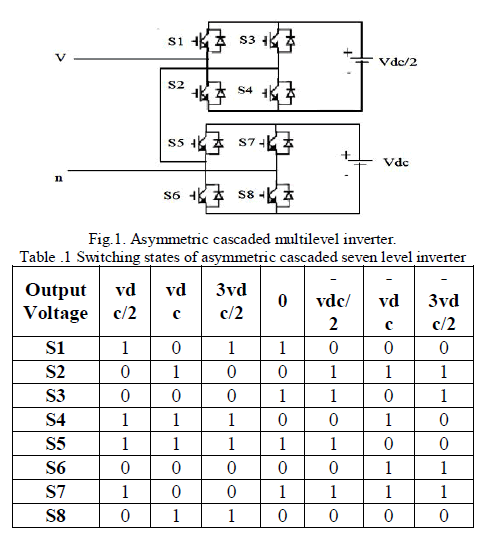
| Asymmetric multilevel have the same topology as symmetric multilevel inverters. They differ only in the rating of input dc voltages and control strategies[20][8]. For many applications it is difficult to use separate dc sources and too many dc sources will require many long cables and could lead to voltage imbalance among the dc sources. To reduce the number of dc sources required for the cascaded H-bridge multilevel inverter, a scheme is proposed which uses lesser number of bridges. This scheme therefore provides the capability to produce higher voltages at higher speeds with low switching frequency which has inherent low switching losses and high converter efficiency[8]. A seven-level asymmetric cascaded H bridge multilevel inverter has two H-bridges for each phase. The DC source for the first H-bridge (H1) is Vdc/2, while the DC source for the second bridge (H2) is Vdc. The circuit diagram of seven level cascaded MLI is shown in Fig.1. The switching states of asymmetrical seven level output voltage is given in the Table.1. |
 |
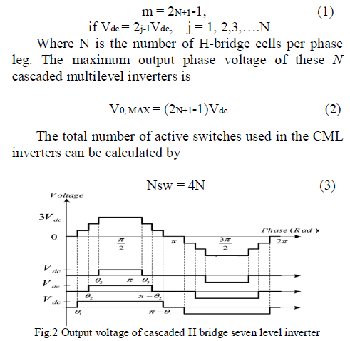
| The number of voltage levels (m) in the phase voltage of symmetrical CMLI inverter can be found from |
 |
SELECTIVE HARMONIC ELIMINATION PWM |
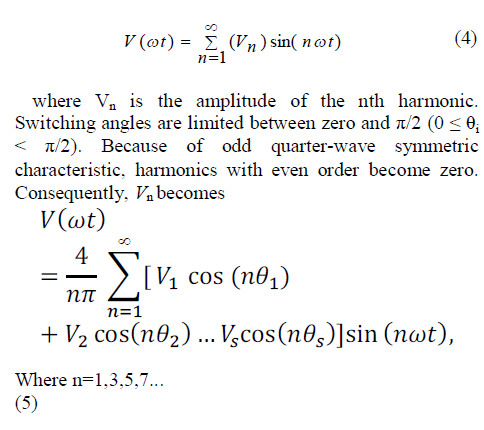
| The popular selective harmonic elimination method is also called fundamental switching frequency method which is based on the harmonic elimination theory[1]. A multilevel converter can produce a quarter-wave symmetric stepped voltage waveform synthesized by several DC voltages as shown in Fig.2 . By applying Fourier series analysis, the output voltage can be written as |
 |
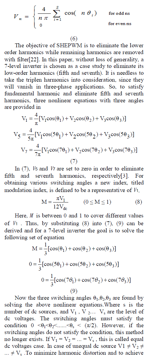 |
| adjustable amplitude of the fundamental component, up to s-1 harmonic contents can be removed from the voltage waveform. In general, the most significant lowfrequency harmonics are chosen for elimination by properly selecting angles among different level converters, and high-frequency harmonic components can be readily removed by using additional filter circuits. To keep the number of eliminated harmonics at a constant level, all switching angles must satisfy the condition 0 < θ1 < θ2 <......< θs < (π/2) or the (THD) increases dramatically. Due to this reason, this modulation strategy basically provides a narrow range of modulation index, which is one of its disadvantages. |
BEE ALGORITHM |
| Artificial Bee Colony Algorithm (ABC) is natureinspired metaheuristic, which imitates the foraging behaviour of bees. ABC as a stochastic technique is easy to implement, has fewer control parameters, and could easily be modify and hybridized with other metaheuristic algorithms. Due to its successful implementation, several researchers in the optimization and artificial intelligence domains have adopted it to be the main focus of their research work[6]. Interestingly, ABC has been tailored successfully, to solve a wide variety of discrete and continuous optimization problems[19]. Some other works have modified and hybridized ABC to other algorithms, to further enhance the structure of its framework. |
| The major advantages which ABC holds over other optimization algorithms include its, |
| • Simplicity, flexibility and robustness. |
| • Use of fewer control parameters compared to many other search techniques. |
| • Ease of hybridization with other optimization algorithms. |
| • Ability to handle the objective cost with stochastic nature. |
| • Ease of implementation with basic mathematical and logical operations. |
| The ABC algorithm is a swarm based, meta-heuristic algorithm based on the model first proposed by on the foraging behaviour of honey bee colonies. The model is composed of three important elements: employed and unemployed foragers, and food sources[6]. The employed and unemployed foragers are the first two elements, while the third element is the rich food sources close to their hive. The two leading modes of behaviour are also described by the model. These behaviours are necessary for self organization and collective intelligence: recruitment of forager bees to rich food sources, resulting into positive feedback and simultaneously, the abandonment of poor sources by foragers, which causes negative feedback. |
| The ABC consists of three groups of artificial bees: employed foragers, onlookers and scouts. The employed bees comprise the first half of the colony whereas the second half consists of the onlookers. The employed bees are linked to particular food sources. In other words, the number of employed bees is equal to the number of food sources for the hive. The onlookers observe the dance of the employed bees within the hive, to select a food source, whereas scouts search randomly for new food sources. Analogously in the optimization context, the number of food sources (that is the employed or onlooker bees) in ABC algorithm, is equivalent to the number of solutions in the population. Furthermore, the position of a food source signifies the position of a promising solution to the optimization problem, whereas the quality of nectar of a food source represents the fitness cost (quality) of the associated solution. |
| The search cycle of ABC consists of three rules: (i) sending the employed bees to a food source and evaluating the nectar quality; (ii) onlookers choosing the food sources after obtaining information from employed bees and calculating the nectar quality; (iii) determining the scout bees and sending them onto possible food sources. The positions of the food sources are randomly selected by the bees at the initialization stage and their nectar qualities are measured. The employed bees then share the nectar information of the sources with the bees waiting at the dance area within the hive. After sharing this information, every employed bee returns to the food source visited during the previous cycle, since the position of the food source had been memorized and then selects another food source using its visual information in the neighbourhood of the present one. At the last stage, an onlooker uses the information obtained from the employed bees at the dance area to select a food source. The probability for the food sources to be selected increases with increase in its nectar quality. Therefore, the employed bee with information of a food source with the highest nectar quality recruits the onlookers to that source. It subsequently chooses another food source in the neighbourhood of the one currently in her memory based on visual information (i.e. comparison of food source positions). A new food source is randomly generated by a scout bee to replace the one abandoned by the onlooker bees. |
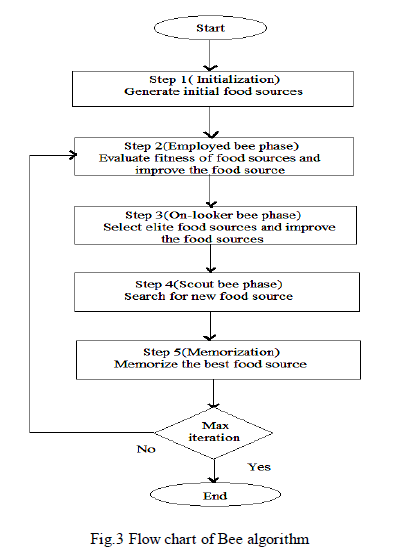 |
| In this algorithm, food sources are considered as possible solutions to a problem. The food source is a Ddimensional vector, where D is the number of optimization variables. The amount of nectar in a food source determines the value of fitness[3]. The basic flowchart of BA is shown in Fig.3. In step 1, random initial food sources are generated. The number of initial food sources is half of the bee colony. In step 2, employed bees are sent to the food sources to determine the amount of nectar and calculate its fitness. For each food source, there is only one employed bee. So, the number of food sources is equal to the number of employed bees. In addition, the employed bees modify the solutions, saved in memory, by searching in the neighbourhood of its food source. The employed bees save the new solution if its fitness is better than the older one. Employed bees go back to the hive and share the solutions with the onlooker bees. In step 3, on-looker bees, which are another half of the colony, select the best food sources using a probability-based selection process. Food sources with more nectar attract more on-looker bees. On-looker bees are sent to the selected food sources. The on-looker bees improve the chosen solutions and calculate its fitness. Similar to employed bees, the on-looker bees save a new solution if its fitness is better than an older solution. In step 4, the food sources that are not improved for a number of iterations are abandoned. |
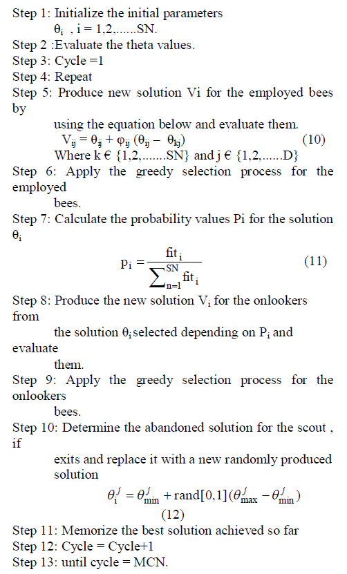
| So, the employed bee is sent to find new food sources as a scout bee. The abandoned food source is replaced by the new food source. Finally, in step 5, the best food source is memorized. The maximum number of iterations is set as a termination criterion which is checked at the end of iteration. If it is not met, the algorithm returns to step 2 for the next iteration.The algorithm for SHEPWM technique to obtain the optimum theta value is given below. |
| A. Bee algorithm in solving SHEPWM |
 |
SIMULATION STUDY |
| The simulation of three phase asymmetric cascaded multilevel inverter is carried out using MATLAB/SIMULINK it is shown in fig.4. The IGBT switching are used as a switching devices. The frequency of output voltage is 50 Hz. In practise the input dc voltage source is available as distributed energy resources like PV-system solar energy. If the available source is ac then rectifier circuit is used in the input. In this work the fundamental frequency switching scheme is used. In this method, the switching angles can be obtained to eliminate the selected harmonics or minimization of total harmonic distortion. |
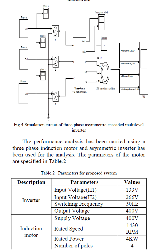 |
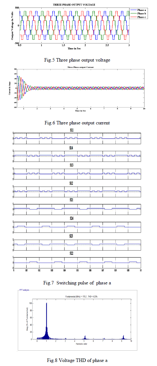
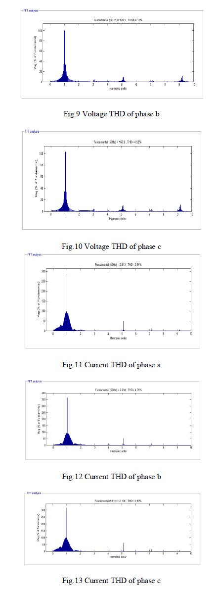
| The three-phase output voltage and current waveform are obtained from the VI measurement block. Fig.5 and Fig.6 represents the phase voltage and current waveform. The switching states of each switch which are represented, has a pulse waveform with respect to the time period in Fig.7.The THD of voltage and current in each phase has been analysed and compared with the conventional system. Fig.8 to Fig.10 shows the voltage THDvalue of each phase leg a, b, c. Figure 6.11 to Fig.13 shows the current THD value of each phase leg a,b,c. |
 |
 |
CONCLUSION |
| A three phase asymmetric cascaded H- bridge multilevel inverter fed three phase induction motor uses asymmetric sources for producing desired multilevel voltage is simulated. A fundamental frequency switching control algorithm was developed and implemented. The FFT analysis of phase voltage shows that the lower order harmonics have been reduced and also higher order harmonics are eliminated. The total harmonic distortion is reduced considerably. This proposed topology requires lesser number of switching devices hence reduces the initial cost and complexity. |
References |
|