ISSN ONLINE(2319-8753)PRINT(2347-6710)
ISSN ONLINE(2319-8753)PRINT(2347-6710)
Donghoon Ban1, Sungho Jin2 and Jaeseung Hong3
|
| Related article at Pubmed, Scholar Google |
Visit for more related articles at International Journal of Innovative Research in Science, Engineering and Technology
A brake system is a nonlinear system which applies different compressive force depending on the position of the brake pad. The EMB(electric mechanical brake) used in passenger vehicles cannot detect the compressive force without a sensor. Therefore, it has different operating times at the same distance because the brake caliper applies different force depending on the position of the brake pad. A position controller for the EMB system was developed to control the operating time robustly at the same distance. A vector control method was used to operate the motor. The result of the position controller was used as the Q axis reference for the vector control method. The PI gain of the position was defined differently to meet the same operating time of the motor on each sector. In addition, the interval value between each position was calculated using an interpolation method. A PI gain of the position controller was tuned using the MATLAB tool, and the reliability of the position controller was verified through a simulation in the MATLAB. The verified PI controller was installed in an EMB system. The operating times were measured on each sector, showing that they were nearly identical. The proposed PI scheduling method was confirmed to have robust characteristics in a nonlinear EMB system with different amounts of compressive force depending on the position of the brake pad.
Keywords |
| EMB, Vector control, PI control, Gain scheduling, Motor-control, Interpolation |
INTRODUCTION |
| The various replacements of hydrodynamic systems are being developed to solve the environmental problems associated with these systems. More electrical components are also being introduced into vehicles as convenience and safety are more emphasized in cars. The EMB system is replacing the former hydrodynamic brake system. This will increases fuel efficiency and mitigate the aforementioned environment problem by removing the oil, pipelines and pumps related to the former system. The new system has been installed in a prototype vehicle thus far because certain safety issues remain. Owing to these issues, the change from the hydrodynamic system to the electric system has been challenging. The EMB system is a nonlinear system which applies different compressive force depending on the position of the brake pad. The EMB system operates when the brake caliper is operated by the motor, the brake caliper pushes the brake pad, and the brake pad makes the vehicle stop. A hydrodynamic brake system can operate the brake caliper using sufficient force due to the high oil pressure. However, the EMB system cannot measure the force of the brake caliper, and some difficulty can arise depending on the position of the brake pad. Thus, an EMB system which has the same PI gain has different operating times for each sector. It cannot secure both the response time and position of brake pad braking capabilities. Hence, robust control is difficult in an EMB system, which is nonlinear. The PI gain of the PI controller regarding the position of the brake pad was defined to have same operating time in an EMB system.A simulation was performed to verify the reliability of the PI controller using the MATLAB tool. A motor controller was developed using a vector control method.Theposition controller for an EMB system was developed by the PI control method. The result of the position controller was used as the Q-axis reference in the vector control method. The actual operating time was measured after installing the position controller in an EMB system. |
RELATED WORK |
| There are many PI controllers in the industry and many papers about the PI gain control are published. A PI controller which has a unique PI gain is very difficult to meet a performance of system. There are two main solutions to solve the problem. The first group is studying methods using the FUZZY [1]. Whereas the second group is studying solutions using the gain scheduling method in [2] and in [3]. A speed controller using a gain scheduling is shown in [4] and in [5]. Additionally, a vector control for operating a motor is being studied in [5] and in [6]. |
EMB SYSTEM |
1. Interpolation |
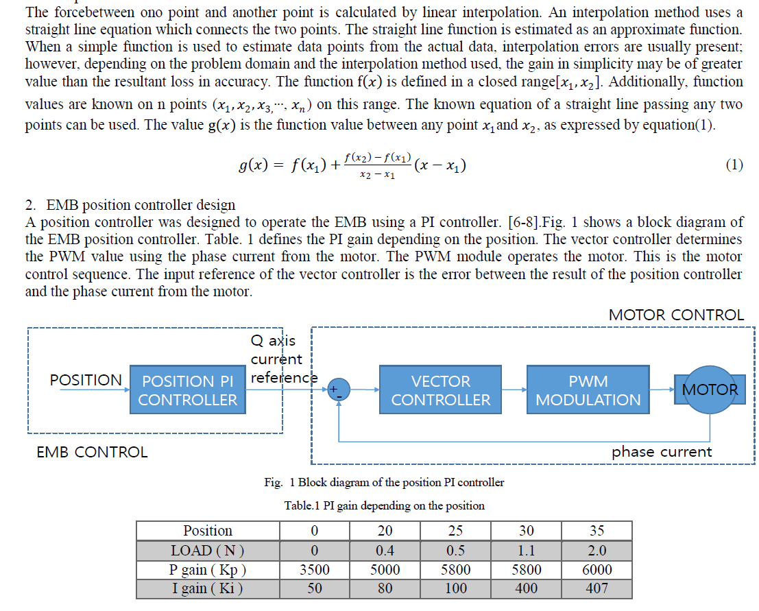 |
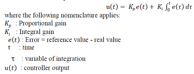
| Each P and I gain values is designed differently on each sector to meet the same operating time at the same distance due to the different compressive force depending on the position between the pad and the disk. The PI controller calculates the error between the actual value and the reference value. The PI gain cam adjust the response time and the setting time. The PI control equation is named after its two correcting terms, whose sum constitutes the manipulated variable. The proportional and integral are summed to calculate the output of the PI controller. Equation (2) is the final form of the PI equation. |
 |
EMB SYSTEM |
1. EMB position controller design in MATLAB |
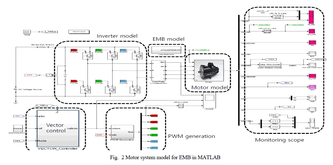
| Fig. 2 shows the EMB system designed using the MATLAB tool. The vector control method is operated in the motor controller. The load of the motor is given by the EMB model. The position controller is designed using the PI controller, and the result is used as the reference of the Q-axis current. The function of each of the labelled blocks is as follows: |
| 1) Reference position: The required position is set using a constant block. |
| 2) PI position block: The error signal is obtained by subtracting the reference position from the real position. For the PI control, MATLAB’s library is used. |
| 3) Motor block: The electrical and mechanical equation of a PMSM. |
| 4) Vector control block: The inputs to this subsystem are the required values of the direct axis(Id), the quadrature axis(Iq) current and the real-time value of theta which is fed back. The direct axis component of the stator current produces useless compression force. Ideally, we would prefer if the direct axis component is 0. Hence, we set the required value of Id to a constant value of 0. |
| 5) Sinusoidal PWM block: This subsystem generates the six PWM waveforms for the FET circuit. |
| 6) EMB model: The load is modelled as an EMB whose value is denoted in force (N). This load force is used in the main motor subsystem to compute other quantities. |
| 7) FET circuit: A three-arm, 6-FETinverter circuit is implemented. The gating pulses (PWM) are provided by the sinusoidal PWM control subsystem. |
| 8) Scope blocks are used to observe the various waveforms in real time. |
| 9) The speed computed by the PMSM model block is in radians/sec. However, for the sake of user convenience, it is converted to RPM. |
| 10) Position block: The position computed by the theta of the PMSM. |
 |
2. Configuration of an actual controller and an actual inverter |
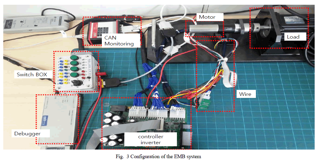
| An actual controller and an actual inverter in a motor were developed to operate the EMB system. Fig. 3 shows the controller and the inverter for the EMB. The EMB system consists of a control board, an inverter board, CAN monitoring equipment, wiring, a switch-box, the motor, and load equipment. Three FETs were connected in parallel to supply sufficient power to allow the inverter to supply the current required by the motor. The control board and the inverter board can operate the motor. The CAN monitoring equipment can monitor the variables of the software in the motor control. The control board was controlled by the switch box, which has 4 switches and 1 potential meter. The load equipment applies the load. The motor is identical to that used in the EMB. The wire has the hall signal and the power of the motor. |
 |
EXPERIMENTAL RESULTS |
1. Simulation Result |
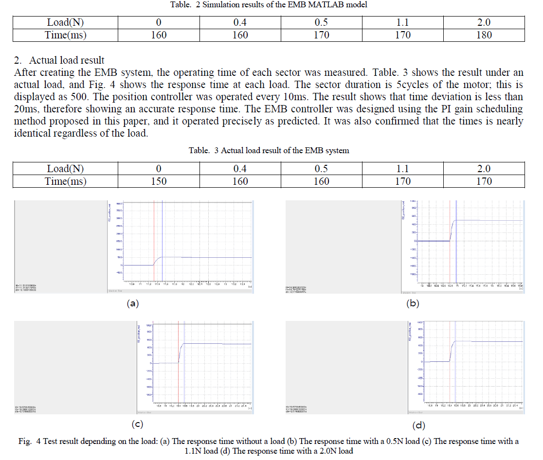
| An EMB controller has the PI gain differently depending on the load. It designed using the EMB model and that was simulated with the time between each sector measured. It was confirmed that there were no differences in time between the initial position and the final position. The initial position has almost no load. The final position has a load close to the maximum load. Table. 2 shows the result of the simulation. When the motor moves a distance equal to 5 cycles of the motor, the operating times are nearly identical. The EMB controller operates every 10ms; hence, variation of 20ms is minor. |
 |
CONCLUSION |
| A brake system is a nonlinear system which applies different amounts of force depending on the brake pad position. An EMB system cannot control the force directly because it cannot detect the force; thus, it has different operating times for each position. A position controller for an EMB system was designed to operate robustly in any position. A three phase BLAC motor was controlled using a vector control method. The output of the position controller was used as the current reference of the Q axis. The PI gain was designed differently to meet the same operating time for each sector, and the reliability of the PI controller was verified in a MATLAB simulation. The designed PI controller was installed into an EMB system and the operating time was measured depending on the load. The operat ing times were nearly identical. So the proposed PI position controller with the scheduling method has been robust and accurate. |
ACKNOWLEDGMENTS |
| This work was supported by the DGIST R&D Program of the Ministry of Science, ICT and Technology of Korea(15- RS-03). |
References |
|