ISSN ONLINE(2319-8753)PRINT(2347-6710)
ISSN ONLINE(2319-8753)PRINT(2347-6710)
Dr.S.L.V. Prasad1, Prof V.Pandurangadu2, Dr.P.Manoj Kumar3, Dr G. Naga Malleshwara Rao4
|
| Related article at Pubmed, Scholar Google |
Visit for more related articles at International Journal of Innovative Research in Science, Engineering and Technology
The object of this study is to investigate the technique to enhance the air swirl to achieve betterment in engine performance and emission in a direct injection (DI) single cylinder diesel engine. In order to achieve the different swirl intensities in the cylinder, three design parameters have been selected: the cylinder head, piston crown, and inlet manifold. In order to research the intensification of swirl in the cylinder, series of experiments are conducted by making straight grooves in the cylinder head. In this work three different configurations of cylinder heads i.e. in the order of number of grooves 1, 3, 6 are used to intensify the swirl for better mixing of fuel and air and to enhance the performance of the engine
Keywords |
| Single Cylinder Diesel Engine, Swirl, Cylinder Head, Performance |
INTRODUCTION |
| The combustion efficiency in the combustion chamber depends on the formation of homogeneous mixture of fuel with air. The formation of homogenous mixture depends on the amount of swirl created in the combustion chamber. This further increases the thermal efficiency of the engine. This investigation leads to improvement in performance, combustion and emission characteristics of a D.I diesel engine through methods enabling improvement in ignition characteristics of the fuel by generating turbulence in the cylinder, for the achievement of better fuel air mixing To enhance the efficiency of an engine it is important to optimize thermal efficiency, which is obtained at the highest possible compression ratio. However, if the compression ratio is too high, there is a chance to have knock, which should be avoided atall cost. A solution for this problem is to promote rapid combustion, to reduce the available time for the self-ignition to occur [1]. For the promotion of rapid combustion, sufficient large-scale turbulence (kinetic energy) is needed at the end of the compression stroke because it will result in a better mixing process of air and fuel and it will also enhance flame development. However, high turbulence leads to excessive heat transfer from the gases to the cylinder walls, and may create problems of flame propagation [2] [3] [4]. The key to efficient combustion is to have sufficient swirl in the combustion chamber prior to ignition The Swirl can be generated in the diesel engine by modifying three parameters in the engine, they are the cylinder head, the piston i.e. modification of combustion chamber and the inlet manifold [5]. Lin.et.al [6] has invented a multi impingementwall head is located at the center of the cylinder head to enhance the swirl and squish.Somendersingh [7] has identified a method to improve turbulence in combustion chamber bymaking grooves on the cylinder head, to reduce the heat losses; the burn time needs to be as quick as possible. According to Al-Rousan[8] swirl is generated in the inlet manifold by inserting a loopinside the intake manifolds to increase the swirling in the air during induction. Rasul and Glasgow [9]prepared a convergent-divergent induction nozzle and is tested in order to increase the airflow into the engine, which may increase the overall performance. |
EXPERIMENTAL WORK |
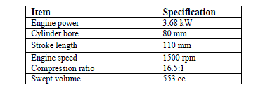
| An attempt is made in this work with different number of channels on the cylinder head of the diesel engine. A number of channels of size 16x3x2 mm are arranged on the cylinder head depends on the locally available technology (Plate1). Experiments are conducted on a diesel engine. Three different sets of channels on the cylinder head are tried in the present work in order to find the best number of channel at which the engine gives optimum performance. The different sets of channelled cylinder heads, which are investigated, are as follows: |
| (i) CH1 : Cylinder head with 1 channel |
| (ii) CH2 : Cylinder head with 3 channels |
| (iii) CH3 : Cylinder head with 6 channels |
 |
 |
RESULTS AND DISCUSSIONS |
| A. Performance Parameters The performance parameters like brake thermal efficiency, volumetric efficiency and exhaust gas temperature are discussed below. |
| [1] Brake Thermal Efficiency |
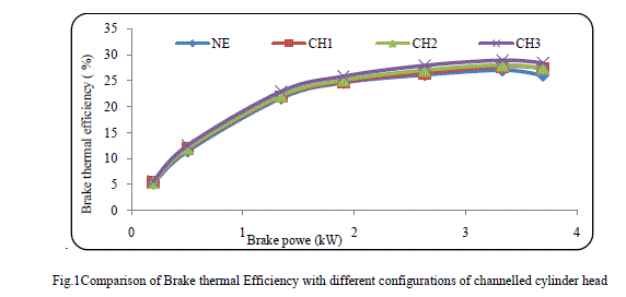
| The variations of brake thermal efficiency with power output for the cylinder head with different configurations are shown in Figure 1. The brake thermal efficiency for normal engine at 3/4 of rated load is 26.1%. It can be observed that the engine with CH3 and CH 2 give thermal efficiencies of 27.9% and 27%, respectively, at 3/4 of rated load. From Figure, it is inferred that the brake thermal efficiencies are increasing with an increase in brake power for configurations that are under consideration. It is also observed that there is a gain of 6.9% with CH3 compared to normal engine. This may be due to the enhanced air swirl in the combustion chamber which resulted in better mixing of fuel and air and as well as complete combustion of the charge in the combustion chamber |
 |
| [2] Volumetric Efficiency |
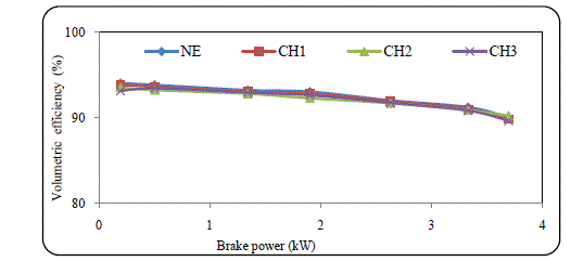
| The variations in volumetric efficiencies against brake power for different configurations are shown in Figure 2. It is inferred that the volumetric efficiencies are decreasing with an increase in brake power for all configurations. It is observed that the volumetric efficiency is lower in the case of CH3, as 89.6% at 3/4 of rated load, whereas for normal engine it is 92%. It is also observed that there is a decrease of 0.3% with CH3 when compared with normal engine. It is observed that the volumetric efficiencies of CH1 and CH 2 lie in between normal engine and CH3. The volumetric efficiency decreases as the air swirl increases in the combustion chamber due to the resistance offered by the airflow against the turbulence generated in the combustion chamber. |
 |
| [3] Brake Specific Fuel Consumption |
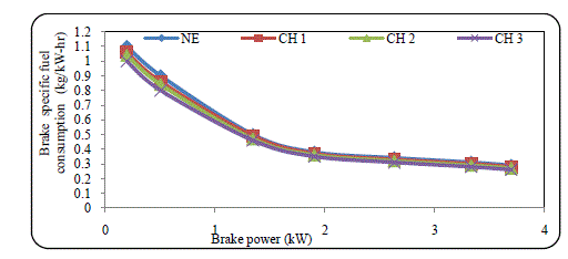
| The variations of brake specific fuel consumption with brake power for different configurations are shown in Figure 3. The brake specific fuel consumption for normal engine at 3/4 of rated load is 0.34 kg/kW-hr. It can be observed that the engine with CH3, CH2 and CH1 give brake specific fuel consumption of 0.31 kg/kW-hr and 0.32 kg/kW-hr and 0.33 kg/kW-hr respectively, at 3/4 of rated load. From Figure 4.3, it is inferred that the brake specific fuel consumption are increasing with an increase in brake power for configurations that were under consideration. It is also observed that the CH3 has the lowest fuel consumption of 8.8% when compared with normal engine. This is because of the complete combustion of charge in the combustion chamber by liberating maximum energy due to the inducement of enhanced air swirl in the combustion chamber. |
 |
| [4] Exhaust Gas Temperature |
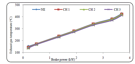
| The comparison of exhaust gas temperature with brake power is shown in Figure 4. The exhaust gas temperatures are higher for CH1 and CH 2 compared to that of CH3. The exhaust gas temperature for CH3 varies from 137°C at no load to 330°C at 3/4 of rated load. For CH 2, the exhaust gas temperature varies from 140°C at no load to 336°C at 3/4 of rated load whereas for normal engine it varies from 151°C at no load to 341°C at 3/4 of rated load. Lower exhaust gas temperature for CH3 can be attributed due to low operating temperature in the combustion chamber resulted by the swirl created in the combustion chamber. It is observed that there is a decrease of 3.2% for CH3 compared with normal engine. |
 |
| B. Combustion Parameters |
| The combustion parameters like ignition delay and peak pressure are discussed below. |
| [5] Ignition Delay |
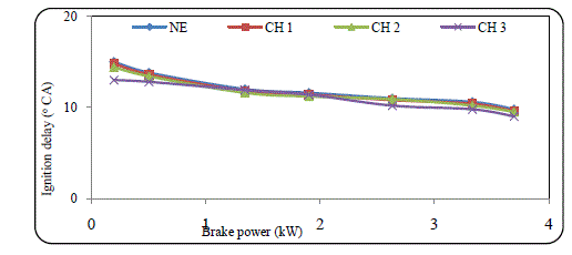
| The variation of ignition delay with brake power for different configurations is shown in Figure 5. It is inferred that ignition delay, decreases with an increase in brake power for almost all configurations. With an increase in brake power, the amount of fuel being burnt inside the cylinder is increased and subsequently the temperature of in-cylinder gases is increased. This may lead to reduced ignition delay in all configurations. However, the ignition delay for diesel fuel was lower under CH3, CH2 and CH1 configurations than the normal engine. It is observed that the ignition delay of CH3, CH2 and CH1 are 10.2o CA, 10.7o CA and 10.8o CA at 3/4 of rated load respectively. The reduction in the ignition delay of CH3 is about 7.3% at 3/4 of rated load when compared to normal engine. This is due to the fast and complete burn of the chargebecause of the flow of high velocity flames through the channels in the cylinder head of the combustion chamber. |
 |
| [6] Cylinder Peak Pressure |
| The variations of peak cylinder gas pressure with brake power for different configurations are given in Figure 6. It is observed that the peak pressure is increased with an increase in brake power. The peak pressures for CH3, CH2 and CH1 are 62 bar, 60.8 bar and 60.2 bar at 3/4 of rated load respectively. The swirl induces the high flame velocities by directing the flame propagation in the channels during compression, the entire fuel-air mixture got ignited and burnt simultaneously. This might be leading to highest peak pressure in CH3 configuration compared to the other configurations. There is anincrease of 2% in pressure when compared with normal engine. |
 |
CONCLUSION |
| The following conclusions are drawn based on the effect of air swirl in the cylinder: |
| The brake thermal efficiency of CH3 is increased by about 6.9% when compared to normal engine at 3/4 of the rated load. |
| The drop in volumetric efficiency of CH3 is more and is about 3.2 % when compared normal engine at 3/4 of the rated load. |
| The improvement in brake specific fuel consumption of CH3 is about 8.8% when compared normal engine at 3/4 of the rated load. |
| The exhaust gas temperature with CH3 is minimum than any other and at 3/4 rated load, it is 3.22% less than normal engine. |
| With higher turbulence in the combustion chamber, the reduction in the ignition delay of CH3 is about 7.3% when compared to normal engine at 3/4 of the rated load. |
| With shorter ignition delay and higher turbulence, the peak cylinder pressure is increased by about 3.3% with CH3 when compared to normal engine at 3/4 of the rated load. |
References |
|