International Journal of Innovative Research in Science, Engineering and Technology
ISSN ONLINE(2319-8753)PRINT(2347-6710)
ISSN ONLINE(2319-8753)PRINT(2347-6710)
Ashwanth.S1 and Manikandan.M2
|
| Related article at Pubmed, Scholar Google |
Visit for more related articles at International Journal of Innovative Research in Science, Engineering and Technology
The power quality (PQ) requirement is one of the most significant concerns for power companies and their customers. In this paper, Superconducting Magnetic Energy Storage (SMES) is applied on wind energy conversion systems that are equipped with Doubly Fed Induction Generators (DFIGs) during the presence of voltage sags and swells in the grid side. Without SMES, certain levels of voltage sags and swells in the grid side may cause a critical operating condition that may require disconnection of WECS to the grid. Voltage sags are the one of important power quality problem. The selection of a SMES unit in this project is based on its advantages over other energy storage technologies. Using the Hysteresis current control approach in conjunction with a Neural network controller, the SMES unit fruitfully and effectively enhances the performance of the DFIG during voltage sag and swell events in the grid side. The modeling of the wind energy conversion systems (WECSs) that are equipped with doubly fed induction generators (DFIGs) with SMES is build using MATLAB/Simulink.
INTRODUCTION |
| Power systems have been experiencing spectacular changes in electric power generation, transmission, distribution, and end-user amenities. Ongoing electric load growth and higher power transfer in a largely interconnected network, shows the way to complex and less sheltered power system operation. Power system engineers facing challenges look for solutions to function the system in more a flexible and controllable behavior. So, role of energy storage devices play significant role as Energy storage appears to be beneficial to utilities since it can decouple the instantaneous balancing between the demand and the supply. Therefore it allows the increased asset utilization, facilitates the penetration of renewable sources and improves the flexibility, reliability and efficiency of the grid. Energy storage devices can be classified into two different categories, depending on their application: Short term response energy storage devices and Longterm response energy storage devices. Short term response energy devices includes flywheel, super capacitor, SMES whereas Long term response energy storage devices includes compress air, hydrogen fuel cell, batteries, etc. Here we are more concern with Short term response energy devices. Flywheel and super capacitor are not having as much of power rating and energy rating so they cannot employ for Short time high power application. So in order to overcome this lack, SMES has been used to perk up the performance of power system as it is having high power rating with maximum efficiency than any other energy storage devices. |
| Also, it is well known that conventional resources of energy such as oil, coal, and gas are used predominantly worldwide today. The massive utilization of these energy resources, particularly in meeting the demands of the world’s population for electric power, resulted in adverse effects on the environment for example, air pollution that contributes to global warming and causes human health problems, and acid rain that can cause skin disease, kill living creatures and decrease the lifespan of buildings. Moreover, the demand for energy is increasing because of rapid industrial and technological developments, particularly in developed nations. Industrial development plays a significant role in energy demand because large amounts of energy are required to support industrial systems operations. |
CONFIGURATION OF SMES |
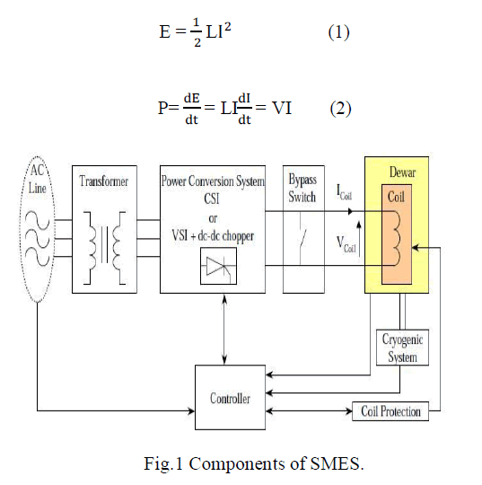
| It was not until 1970s superconducting magnetic energy storage (SMES) was primary proposed as a technology in power systems. Energy is stored in the magnetic field generated by circulating the DC current through a superconducting coil. As can be seen from Fig.1, a SMES system consists of several sub-systems. A large superconducting coil is the heart of a SMES system, which is contained in a cryostat or dewar consisting of a vacuum vessel and a liquid vessel that cools the coil. A cryogenic system is also used to keep the temperature well underneath the critical temperature of the superconductor. An ac/dc PCS is used for two purposes: One is to convert electrical energy from dc to ac, the other is to charge and discharge the coil. Finally, a transformer provides the connection to the power system reduces the operating voltage to acceptable levels for the PCS. |
 |
| For a SMES system, the inductively stored energy (E in Joule) and the rated power (P in Watt) are commonly the given specifications for SMES devices, and can be expressed as before (1)&(2). Coil inductance (L) or PCS maximum voltage (V max) and current (I max) ratings determine the maximum energy/power that can be drawn or injected by a SMES coil. Increasing any of these parameters improves the energy/power capability of SMES. But, there are other factors that need to be taken into consideration which is as shown in below table.1. |
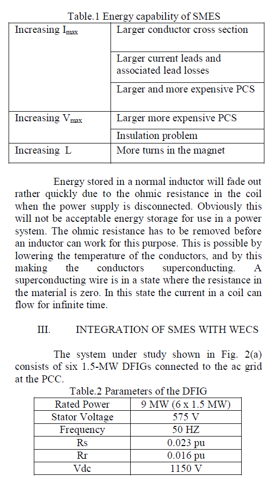 |
| The DFIG consists of an induction generator with stator winding connected directly to the grid through a Y/Δ step-up transformer, whereas the rotor winding is connected to a bidirectional back-to-back insulated gate bipolar transistor (IGBT) VSC, as shown in Fig. 2(b). The grid that is represented by an ideal three-phase voltage source of constant frequency is connected to the wind turbines via a 30-km transmission line and Δ/Y step-up transformer. |
 |
SMES CONTROL APPROACHES |
| Generally, there are two major configurations of SMES, i.e., current source converter (CSC) and VSC. Traditionally, CSC is connected through a 12-pulse converter configuration to eliminate the ac-side fifth and seventh harmonic currents and the dc side sixth harmonic voltage, thus resulting in significant savings in harmonic filters. However, because this configuration uses two 6- pulse CSCs that are connected in parallel, its cost is relatively high. The VSC, on the other hand, must be connected with a dc–dc chopper through a dc link, which facilitates energy exchange between the SMES coil and the ac grid. The total cost of the switching devices of the CSC to be 173% of the switching devices and power diodes required for equivalent capacity of the VSC and the chopper. Moreover, a VSC has a better selfcommutating capability, and it injects lower harmonic currents into the ac grid than a comparable CSC. The use of IGBTs in this configuration is more beneficial than GTO since the switching frequency of an IGBT lies on the range of 2–20 kHz, whereas, in case of GTO, the switching frequency cannot exceed 1 kHz. |
| The proposed SMES configuration used in this paper consists of a VSC and dc–dc chopper. The converter and the chopper are controlled using a hysteresis current controller (HCC) and a Artificial Neural network Controller (ANC), respectively. |
A.HCC |
| The HCC is widely used because of its simplicity, insensitivity to load parameter variations, fast dynamic response, and inherent maximum-currentlimiting characteristic. The basic implementation of the HCC is based on deriving the switching signals from the comparison of the actual phase current with a fixed tolerance band around the reference current associated with that phase. However, this type of band control is not only depending on the corresponding phase voltage but is also affected by the voltage of the other two phases [36]. The effect of interference between phases (referred to as interphase dependence) can lead to high switching frequencies. To maintain the advantages of the hysteresis methods, this phase dependence can be minimized by using the phase-locked loop (PLL) technique to maintain the converter switching at a fixed predetermined frequency level. The proposed SMES with an auxiliary PLL controller is shown in Fig. 3. The HCC is comparing the three-phase line currents (Iabc) with the reference currents (I* abc), which is dictated by the I*d and I*q references. |
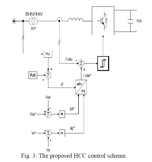 |
| The values of I*d and I*q are generated through conventional PI controllers based on the error values of Vdc and Vs. The value of I*d and I* q is converted through Park transformation (dq0 − abc) to produce the reference current (I* abc). |
B.ANN |
| The interest for artificial neural networks arises from the idea that the study of them may help us understand the brain, human cognition and perception and has lead to development of systems with improved functionality to solve complex problems. A wish for developing a technology able to efficiently perform the same tasks as humans, but more accurately, faster and without ever getting tired or minding working in unsustainable conditions has been a driving force for researchers in academies and in the industry. It has been proven that neural networks can be used to efficiently solve many problems that are difficult using conventional programming techniques. Artificial neural networks are a very simplified model of biological neural networks. |
| There are many theories on how biological neural processing works but the main characteristics have been determined and used to implement the artificial ones. Input neurons are fed with the input signals and are further connected via weighted connections to next layer. Multi-layered feed forward network is a natural and important extension of single layered networks, where at least one layer has been placed between the input and output layers. |
SIMULATION RESULTS & DISCUSSION |
A. Voltage Sag Event |
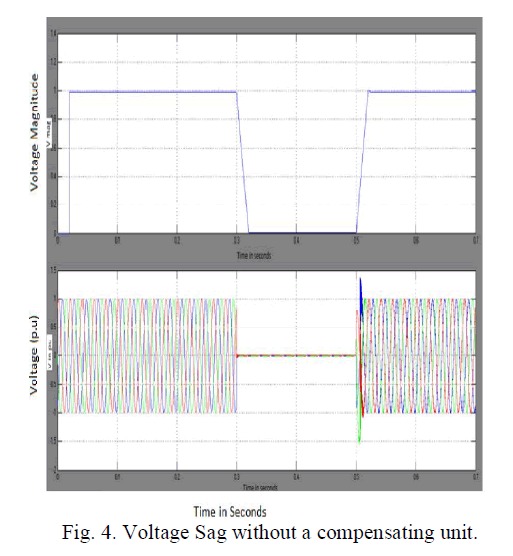
| Voltage sag is a decrease to between 0.1 and 0.9 pu in r-m-s voltage or current at the power frequency for durations of 0.5 cycles to 1.0 minute. Voltage sags are usually associated with system faults but can also be caused by switching of heavy loads or starting of large motors. A voltage sag lasting for 0.2 s is applied at t=0.3 s at the grid side of the system under study. Without the compensating unit, the voltage sag can be occurred at the time between 0.3s to 0.5s. Then the magnitude of the voltage can be reduced to zero for that particular fault time is shown in Fig. 4. This will leads to misoperation of the loads or sometimes tripping of the load circuits |
 |
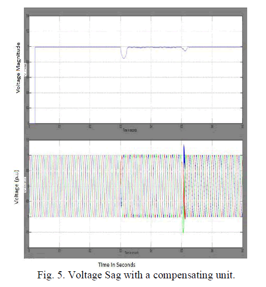
| With the inclusion of the compensating unit, the voltage sag at the fault time of 0.3 to 0.5s shall cleared and the magnitude of the voltage can be maintained on the same level before and after the faults is shown in Fig. 5. Also as compared to the conventional methods, the proposed simulation shows the less variations during clearance of faults at the time between 0.3s to 0.5s. |
 |
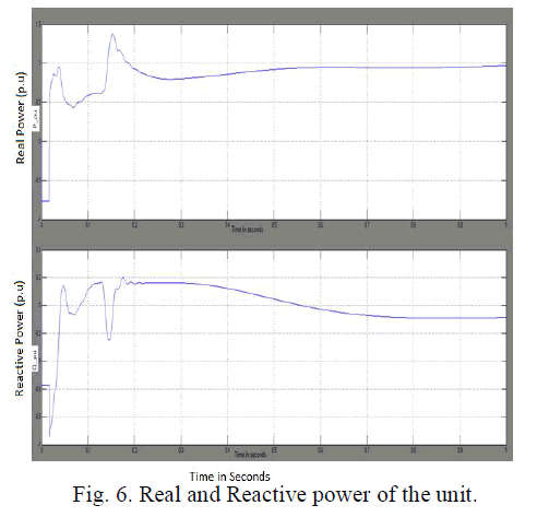
| The amount of reactive power absorbed by the DFIG is lesser with SMES connected to the PCC, since the voltage profile at the PCC is rectified to a level below 1pu with the connection of the compensating unit while this voltage will remain above 1pu without compensating unit connected to the PCC can be shown in Fig. 6. |
 |
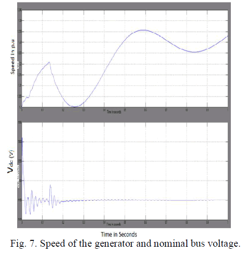
| The Speed of the generator and nominal bus voltage during which the fault can be cleared by means of compensating unit is shown in the Fig.7. The nominal bus voltage become smooth with the connection of compensating unit in the wind generation systems. |
 |
B. Voltage Swell Event |
| A swell is defined as an increase in r-m-s voltage or current at the power frequency for durations from 0.5 cycles to 1.0 minute. Typical magnitudes are between 1.1 and 1.8 pu. As with dips, swells are usually associated with system fault conditions, but they are much less common than voltage dips. Swells can also be caused by switching off a large load or switching on a large capacitor bank. |
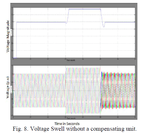 |
| In this simulation, a voltage swell is applied by increasing the voltage level at the grid side to 1.35 pu. The voltage swell is assumed to start at t= 0.3 s and lasts for 0.2s. In this event, DFIG generated power will increase upon the swell occurrence and will be reduced when it is cleared. Without the compensating unit, the magnitude of the voltage can be increased beyond 1 pu for that particular fault time is shown in Fig. 8. This will leads to failure of fuse or sometimes sensitive loads too. With the inclusion of the compensating unit, the voltage swell at the fault time of 0.3 to 0.5s shall cleared and the magnitude of the voltage can be maintained on the same level before and after the faults. |
| The following general observations can be concluded: |
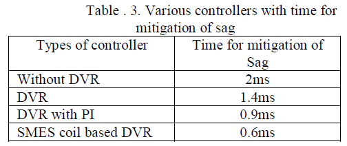 |
| From the Table 3. time taken for mitigation of sag with the SMES coil based DVR takes only 0.6ms, which is more advantageous over all other controllers. |
CONCLUSION |
| A new control algorithm along with a new application of the SMES unit to improve the transient response of WTGs equipped with DIFG during voltage sag and voltage swell events has been proposed. Simulation results have shown that the SMES unit is very effective in improving the dynamic performance of a power system with wind turbine equipped with DFIG during voltage sag and voltage swell at the grid side. The proposed control algorithm of the SMES unit is simple and easy to implement. Also the results shows that the system has greater reliability compare to system without SMES. Thus the system with SMES is able to provide stable and less variations in the output voltage to the connected loads. |
References |
|