ISSN ONLINE(2319-8753)PRINT(2347-6710)
ISSN ONLINE(2319-8753)PRINT(2347-6710)
Sankarapandian. G1 and Prabakaran. R2
|
| Related article at Pubmed, Scholar Google |
Visit for more related articles at International Journal of Innovative Research in Science, Engineering and Technology
Acoustic grating technology for the purpose of removing slag and fouling deposits in coal-fired utility power plant boilers offers great potential. Conventional slag removal methods including soot blowers and water lance cleaning devices are being only partially successful in removing deposits especially from the downstream side of heat transfer tube bundles in the convective pass sections. They also require considerable maintenance and reduce boiler efficiency when in use. This paper work helps to experiment and the performance of boiler furnaces by understanding the effects of heat absorption, increased draft loss, over-heating of tubes and heat lost. This thereby, confirmed the effect of the lost performance of the overall boiler, and hence helps to develop means of eliminating the growth of either slagging or fouling or both (opacity). This is often found when a furnace starves of air or combustion of such materials as thin paper where fly ash partially fills the combustion chamber. It is necessary to remove this accumulation daily in order to increase efficiency of Boiler and life of tubes/coils. Effective cleaning by using acoustic methods is suggested solutions for cleaning Boiler Tubes/Coils, which improves Boiler efficiency by increasing heat transfer rate.
INTRODUCTION |
Coal Fired Thermal Power Station |
| A thermal power station works on the basic principle that heat liberated by burning fuel is converted into mechanical work by means of a suitable working fluid. The mechanical work is converted into electric energy by the help of generators. A coal based thermal power plant converts the chemical energy of the coal into electrical energy. This is achieved by raising the steam in the boilers, expanding it through the turbine and coupling the turbines to the generators which converts mechanical energy into electrical energy. |
| A thermal power station is a power plant in which the prime mover is steam driven. Water is heated, turns into steam and spins a steam turbine which drives an electrical generator. After it passes through the turbine, the steam is condensed in a condenser and recycled to where it was heated; this is known as a Rankine cycle. The greatest variation in the design of thermal power stations is due to the different fossil fuel resources generally used to heat the water. Some prefer to use the term energy centre because such facilities convert forms of heat energy into electrical energy. Certain thermal power plants also are designed to produce heat energy for industrial purposes of district heating, or desalination of water, in addition to generating electrical power. Globally, fossil fuelled thermal power plants produce a large part of man-made CO2 emissions to the atmosphere, and efforts to reduce these are varied and widespread. |
FORMATION AND GROWTH OF ASH DEPOSITS ON HEAT TRANSFER SURFACES |
| When coal or oil is burnt in a boiler the mineral matter, present in the fuel (in an amount reaching even 40-50%), is either deposited as a slag at the bottom of the boiler or, in the form of tiny particles, convected by flue gases to the upper part of the boiler. Some of these particles deposit on cooler surfaces of the combustion chamber or superheaters, some are captured in electrofilters or ejected to the atmosphere. The particles on its way along the boiler are affec- ted by forces of different nature. |
| They are slowed down by gravity and aerodynamic (Stokes) forces, especially in the boundary layers of gases existing at the surfaces. Approach of the particles to these surfaces is helped by thermophoresis and Magnus forces. If the particles have been charged (e.g., by mutual collisions), then their movement to the surface is enhanced by electromagnetic forces (in the presence of electromagnetic fields) or electric forces appearing due to electric induction on the wall (in the absence of electric fields). Being on the surface, the particles are sticking to it due to adhesive forces of electric or Van der Waals origin. Adhesion of the particles is greatly increased by higher roughness of the wall. The forces acting on particles are dependent on the particle diameter so a selection in the size of particles occurs. Greater particles are deposited earlier mainly on the front parts of the surfaces, smaller particles form a de- posit later and on the rear parts of the surfaces (i.e. superheater tubes). |
| The particle surface is often melted which helps in better sticking of the particle to the wall. This also leads to the selection in the chemical composition of particles. The particles with lower melting point are deposited earlier in comparison with those of the higher melting point. In the lower part of the combustion chamber processes of growth and melting of the deposit cause irregular dislodgement of the deposit from the chamber walls or flow of a slag down the chamber. In the upper part of the combustion chamber, as well as on the tubes of radiative and convective superheaters, a constant increase of thickness of the deposit is observed. This increase is at first more rapid (after 1 to 2 hours thickness of the deposit usually reaches half a milimeter), then it is slowed down leading to a certain stabilization in the deposit growth. This phenomenon is attributed to a decrease of thermophoresis when difference in gas and deposit outer surface decreases and to an aerodynamic shape of the deposit that has been formed. Many other factors influence ash deposition . The way the fuel is prepared for combustion and the way it is burnt are some of these factors. The more fuel is pulverized, the higher content of smaller particles in the flue gases and the higher probability of their deposition. The temperature of the flue gases is also of importance. The higher this temperature, the more particles are carried by the gases, and the greater thermo diffusion forces. The increase in the excess air factor causes the lower concentration of ash particles in the flue gases and hampers deposition. The kind of fuel is another factor that is important during ash deposition. The particles formed in the coal fired boilers are greater in diameter and have such chemical composition which leads to a centimetre thick layer of the deposit. The ash deposit that is formed on tube walls of the combustion chamber and on tubes of the radiative super heaters is tightly bound with the tube surface. The particles formed in the oil fired boilers are usually smaller. Their deposition on cool surfaces of the boiler mainly occurs on the radiative and convective superheaters. The ash thickness usually attains the thickness of a few millimetres and is easier to remove from the tubes surface. The higher radiative heat flux in the boiler leads to the surface melting of the deposit which helps in sticking of new particles. If the velocity of the flue gases is increased, then the more ash particles are deposited on the rear sur- face of the tubes. A decrease of tubes distance in the tube banks of the steam or water heaters causes a decrease in flow rate and enhances ash deposition. This often leads to the formation of slag bridges between the tubes. A mutual interaction of deposits in different parts of the boiler has been observed. |
| An increase of ash thickness in the lower part of the boiler and associated with it higher temperature of the flue gases helps in the sintering and melting of deposits in the upper part of the boiler. The start of the boiler operation (e.g. after periodic surveys) or its switch-off causes a dilatation in tubes length and leads to the deposit fall-off. A characteristic variation in ash deposit cross-section along the path of flue gases is schematically shown in Fig.l. Primarily, the deposit is formed on the front part of the tubes (Fig.2) and is difficult to remove from the surface. Then, due to changes in the mean diameter, the chemical composition of ash particles and the velocity of flue gases, the shape of the deposit layer is changing. The greatest thickness of the deposit is moving to the rear part of tubes. The deposit is then less tightly bound to the surface. At the water heaters any deposit is hardly visible . |
INFLUENCE OF ASH-DEPOSITS ON HEAT TRANSFER IN BOILERS |
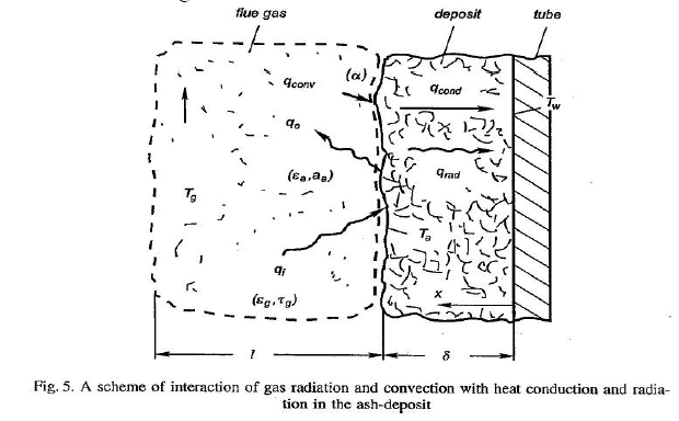
| All heat transfer modes: radiation, convection and conduction are present in the boiler. Ash deposition influences each of them. It changes the geometry of the flue gases flow in heat exchangers of the boiler and causes an increase in the gas velocity. The fly ash suspended in the form of particles in the flue gases changes its radiative heat flux characteristics. The surface of the ash deposit has different radiative properties than the tube surface such that less thermal radiation is absorbed and less emitted. A layer of the ash deposit forms a thermal resistance to the flow of heat by conduction. Subsequent processes of radiation absorption and emission within deposit sublayers cause the hampering of heat flow by radiation in the deposit. For high optical thickness of the deposit radiative transport of heat is of a diffuse nature while thin ash layers can be semi-transparent to high temperature radiation. All discussed processes of heat transfer between the flue gases and the heated surface have been schematically shown in |
 |
Heat transfer between layers of slag to tubes |
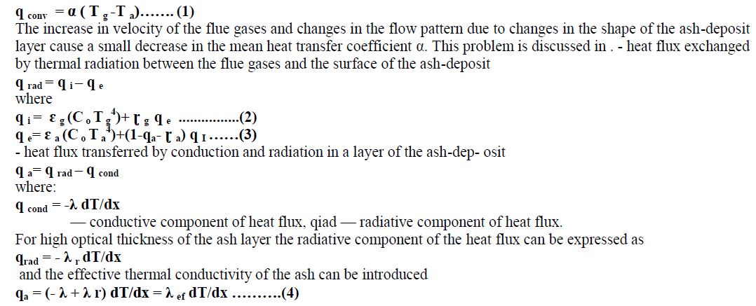
| They can be described by the following formulae: - heat flux exchanged by convection between the flue gases and a surface of the ash-deposit |
 |
 |
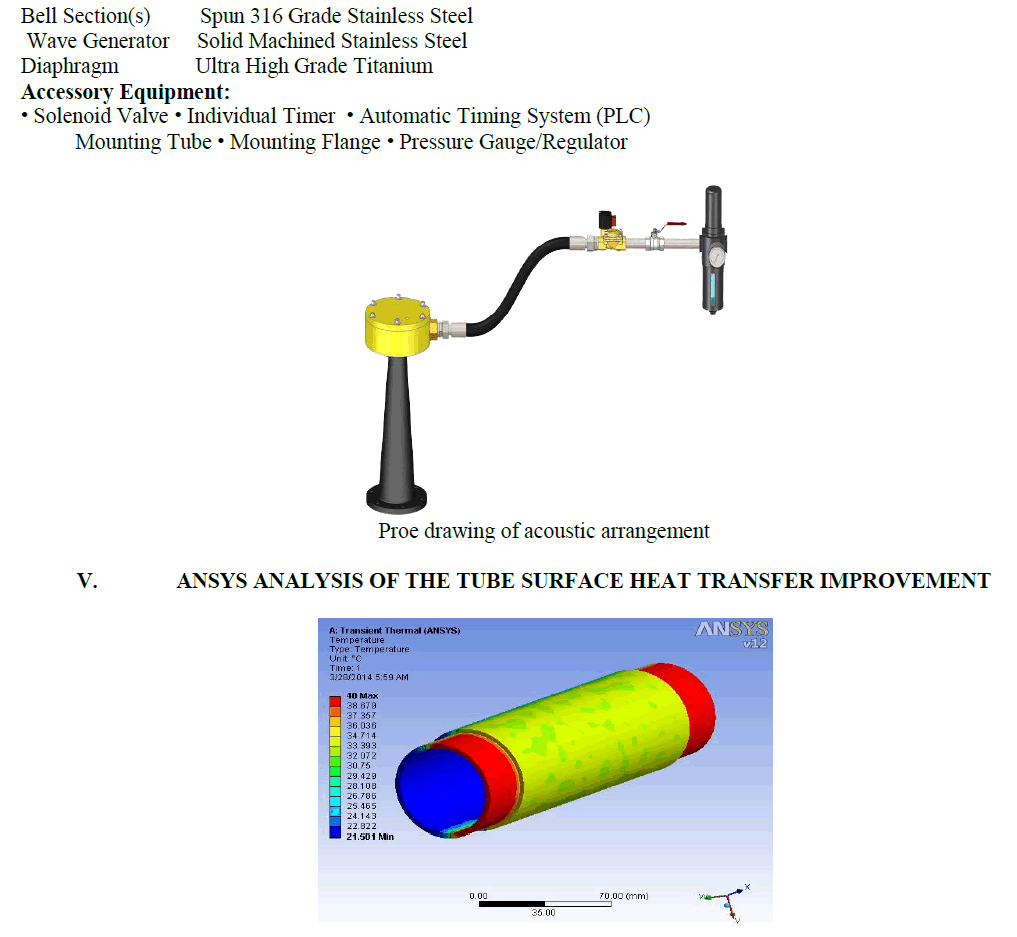
EXPERIMENTAL SETUP OF ACOUSTIC CLEANING MACHINE |
COMPONENTS |
| Material of Construction: |
 |
References |
| BOOKS: 1. Power Plant Engineering By R.K.Rajput 2. Fundamentals Of Heat And Mass Transfer By Incropera; Frank P. 3. Wikipedia 4. U.S. Environmental Protection Manual 5. Google Books & Searches 6. Heat and Mass Transfer by P K Nag 7. CRC Hand Book of Thermal Engineering by Frank Kreith WEBPAGES 8. WWW.WIKIPEDIA.COM 9. WWW.acaa_usa.org/American coal Ash Association 10. www.epa.gov/epa sources 11. www.eei.org 12. www.coalcombustion.com 13. www.rmrc.wisc.edu |