International Journal of Innovative Research in Science, Engineering and Technology
ISSN ONLINE(2319-8753)PRINT(2347-6710)
ISSN ONLINE(2319-8753)PRINT(2347-6710)
Sunilsing Rajput1 and Dr. D.S. Deshmukh2
|
| Related article at Pubmed, Scholar Google |
Visit for more related articles at International Journal of Innovative Research in Science, Engineering and Technology
Regenerative chatter is a self-excited vibration which occurs in milling machines. This is an undesirable phenomenon which occurs in milling machine when they are operating at high speed. They have negative effects, such as poor surface finish, unacceptable accuracy, excessive noise, tool wear and lower Material Removal Rate (MRR). Prediction and control of chatter is very important in milling machine spindle-tool unit, which gives guidance to the machine tool user for an optimal selection of spindle speed and width/depth of cut, which reduces chatter vibration and excess noise which is produced because of high speed operation. In this paper, an experimental investigation is presented of vertical milling machine which is predicted and control by Harmonizer software, which suggests the stable spindle speed and depth of cut for the operator. On the basis of experiments, the Stability lobe diagram is plotted which shows the stable and unstable region for that machine.
Keywords |
| Regenerative Chatter, Chatter frequency,Harmonizer, &SLD |
INTRODUCTION |
| Milling machine is widely used for the higher material removal rate (MRR) operating at very high speed. Because of high speed, dynamic problem occurs in milling machine spindle and tool. As there is relative motion between tool and work piece, various internal and external forces rises in tool and work piece. These forces set up vibration in machine part which is in motion or in rest.Basically three types of vibration occur in machine,free vibration, forced vibration and self-excited vibration [2]. First two vibrations can be easily detected and controlled by using dampers and by other means. But, mainly chatter prediction is major task for the operator while operating at higher speed. It has a very poor surface finish which directly decreases the productivity. |
| Though chatter prediction is tough task, the area of interest of operator is to identify the type of chatter. Chatter is broadly classified in two categories:Primary chatter and secondary chatter.Primary chatter is sub classified as frictional chatter, thermo-mechanical chatter and mode-coupling chatter. Primary chatter is because of the friction between tool and work piece and it diminish with the increase in spindle speed. And secondary chatter is because of the regeneration of waviness of the surface of the work piece. This chatter is called as regenerative chatter. This chatter is also known as self-excited chatter.It is very difficult to avoid regenerative chatter as it increases with the increase in spindle speed and depth of cut. |
| Around 1907, F.W. Taylor [1] stated that chatter is the most obscure and delicate of all problems facing the machinist. Tobias [3]and Tlusty [5] have discovered the first stability analysis on regenerative chatter for the orthogonal cutting process. They obtained stability lobe diagram (SLD) on the basis of stability analysis. It shows the boundary between stable an unstable cut. By using SLD, operator may select chatter free operations for the milling machine. A detailed discussion can be seen in many papers regarding SLD. The main task of this project is to analyse the table spindle speed for the chatter free operation of vertical milling machine.Chatter vibration has various negative effects such as: |
| • Poor surface quality and unacceptable accuracy, |
| • Tool wear and tool damage, |
| • Excessive noise, |
| • Low material removal rate (MRR), |
| • Low productivity rate. |
LITERATURE SURVEY |
| Regenerative chatter is troublesome problem nowadays for machine operators for high accuracy and acceptable surface finish. Based on literature survey, various methods are available for control of chatter. Some methods are analytical, semi analytical and experimental methods. J. Tlusty and M. Polacek [5] presented the theory on regenerative chatter in orthogonal cutting. In this paper, they presented the regenerative chatter depends on the machine tool-work piece system. Altintas and Budak [4] presented analytical method for predicting stability lobes on high speed milling. Based on analytical solution, they have derived various equations for stability lobes. These stability lobes help the operator for the selection of chatter free spindle speed and depth of cut. E Solis[] presented new analyticalexperimental for prediction of stability lobes in high speed milling. P.H. Fassen [7] presented a new method for prediction of chatter. In this paper, a dynamic model is constructed on the basis of several experiments on both the material behavior of the work piece material and machine dynamics. Then a method for prediction of chatter boundaries is proposed and applied to predict chatter boundaries as a function of process parameters like spindle speed and depth of cut. This modeled chatter boundaries are finally compared with the experimental results to validate the results and the stability analysis. For total model, D-partitioning method is used to generate the stability lobes. Guillem Quintana [13] proposed an experimental method for obtaining stability lobe diagram. In this paper, a taper work piece was machined by using milling tool. At specific speed, axial depth of cut increases along the tapered work piece. And at certain point chatter occurs. If measured signal exceeds threshold value, then chatter is detected. The signals are recorded in microphone and then it is analyzed for the chatter frequency. For analyzing chatter frequency various software can be used like Labview, Cutpro [11], Metalmax[9] and Harmonizer [11]. Then FFT can be calculated from audio signals. This graph shows high amplitudes during chatter periods and low sounds during chatter less operations. And based on these results stability lobe diagram can be plotted. |
MECHANISM OF REGENERATIVE CHATTER |
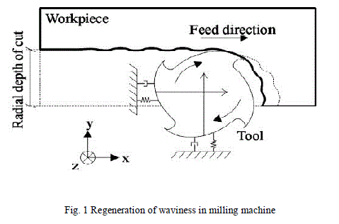
| The chatter vibrations of machine tool occur due to a self-excitation mechanism in the generation of chip thickness during machining operations. Due to the cutter vibrations a wavy surface is left on the surface of the work piece by means of a tooth of cutter.Then the very next tooth strikes the wavy surface and generates the new wavy surface.The phase difference between the two wavy surfaces varies the chip thickness. This increase the cutting forces of cutter. Then system becomes unstable, and chatter vibrations grow until the tool jump out of the cut which results in nonsmooth surface. Thus the chatter vibrations continue which reduces the material removal rate. This theory is presented by Tobias &Tlusty [5]. |
 |
EXPERIMENTAL ANALYSIS |
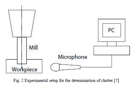
| For performing the experiment on chatter analysis, BFW vertical milling machine is used. Mild steel material is used as work piece on which the operations to be performed. For machining operation, T-max cutter with carbide tips is used. It has 6 numbers of teeth and 3.1416 in tool diameter. And Harmonizer [10] softwareis used for recording and analysing. |
 |
ABOUT HARMONIZER |
| Few years ago, analytical methods of Altintas [4] were used for the prediction of chatter boundaries. Calculating of chatter frequencies were difficult task because of the large numeric calculation. Now a days Various software such as labview, cutpro [11], metalmax [9], and Harmonizer [10] are used in monitoring and recording the data from microphone. In this paper, for the performing of experiments, Harmonizer software is used to calculate chatter frequency. A suitable DAQ assist is used for acquiring the sound signal during machining. The Fast Fourier Transform (FFT) was calculated from audio signal to obtain frequency domain. Then the plotted graph shows high sound level during chatter period and low Sound levels for chatter free operations.Graph also shows the high frequency during chatter operations and low frequency during the chatter free operations.At high chatter frequency it suggests the suitable spindle speed which has chatter less frequency, which helps to operator to perform the chatter free operations on work piece. Then stability lobe diagram is plotted based on the experimental results.The accuracy for prediction of stability lobes are depends on the microphone. If good quality microphone used, then it gives accurate readings which ease the task of operator. Harmonizer software is also available for android and iOS platform which directly suggests the suitable spindle speed by recording the sound by means of built-in microphone. |
SIMULATION AND RESULTS |
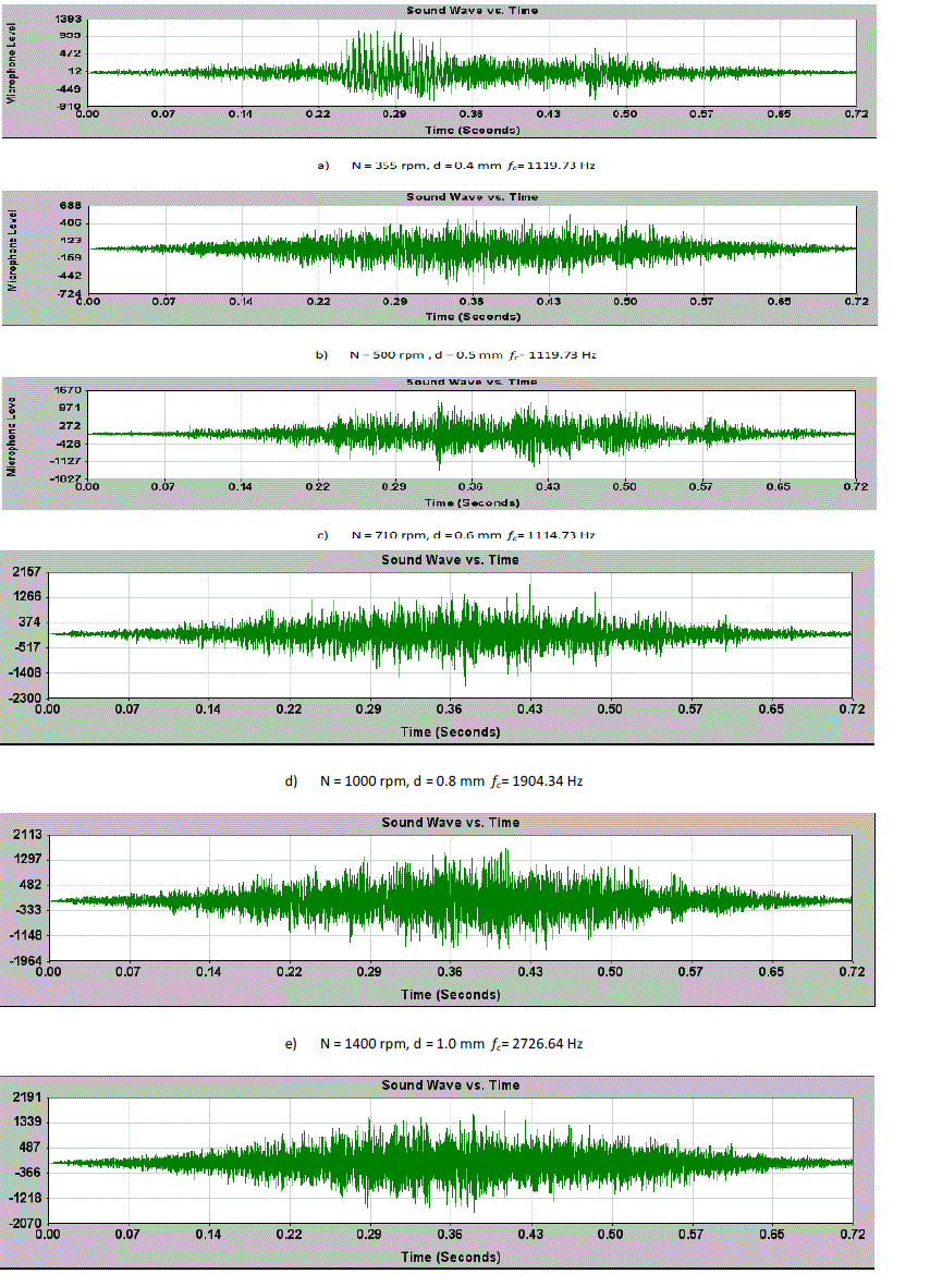
| After recording the sound during machining and analysing it, following frequencies obtained at several spindle speed. All the frequencies are the chatter frequency as they show the presence of chatter. Simulation result shows the presence of chatter during high sound level and low amplitudes during chatter free operations. During chatter period, the frequencies are very high and during chatter free operations frequencies are less. Following simulation results shows that all cutting parameters shows influence on the machining stability (see figure a-f). From the results, it is clear that cutting speed, depth of cut and feed rate have influence on machining stability. In the following figure N represents spindle speed in rpm, d represents depth of cut and fcrepresents the chatter frequency at different cutting parameters. |
 |
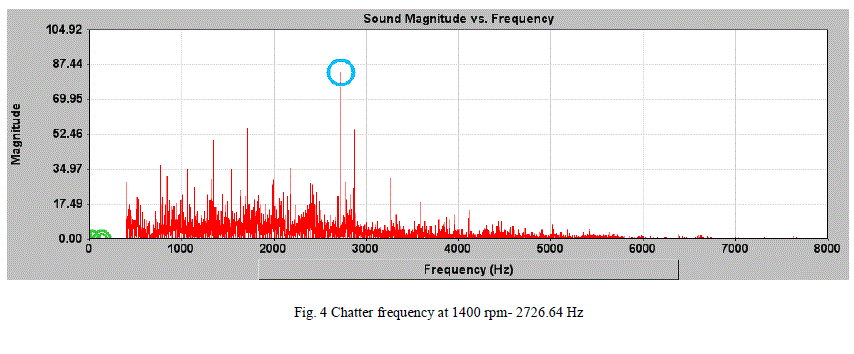 |
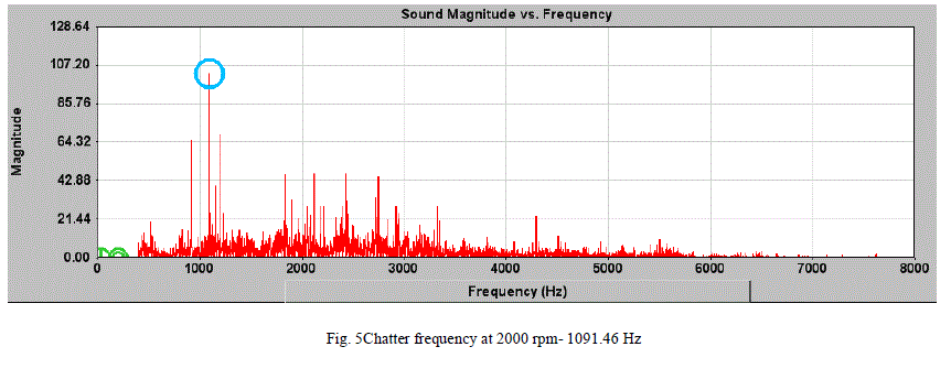
| Figure 4 shows the graph of chatter frequency for spindle speed 1400 rpm. Obtained frequency was 2726.64 Hz. And figure 5 shows the chatter frequency for spindle speed 2000 rpm, where the obtained frequency was 1091.46 Hz. Frequencies for all the spindle speeds are listed in table no. 2. |
 |
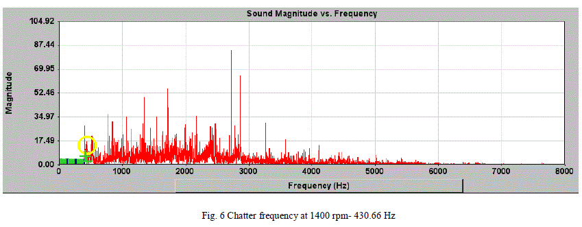
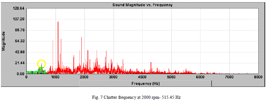
| Figure 6 shows the graph of chatter lessfrequency for spindle speed 1333 rpm. Obtained frequency was 430.66 Hz. And figure 7 shows the chatter less frequency for spindle speed 1937 rpm, where the obtained frequency was 515.45 Hz. Frequencies for all the spindle speeds are listed in table no. 2. |
 |
PLOTTING OF STABILITY LOBE DIAGRAM (SLD) |
| Stability lobe diagram is the design tool which is used for the selection of optimum parameters spindle speed and depth of cut (width of cut). It ensures the chatter free machining operation at high speed and high material removal rate. It is a graph on which spindle speed is plotted on X axis and depth of cut is plotted on Y axis. Fig.7 shows the example of Stability Lobe Diagram. A curve of scallop- shaped separates the stable and unstable region. This area above the curve which are also known as lobes, called as unstable region. And area below the curve is called as stable region. Stable and unstable regions are separated by curve or boundary. Plotting of SLD is not an easy task. Figure 8 shows the Stability Lobe Diagram. |
 |
CONCLUSION |
| The vibrations in milling machines should be minimized for higher material removal rate (MRR). Regenerative chatter is the instability phenomenon must be avoided in high speed milling machines by using stability lobe diagram. SLD suggests the optimal parameters like spindle speed and depth of cut which helps the operator for chatter free operations with high surface finish and greater accuracy. For BFW vertical milling machine, suggested spindle speed is 1933 rpm for the depth of cut 1.2 mm by using T max cutter. |
References |
|