ISSN ONLINE(2319-8753)PRINT(2347-6710)
ISSN ONLINE(2319-8753)PRINT(2347-6710)
S. C. Eze1, C. O. Izelu2, B. U. Oreko3, B. A. Edward4
|
| Related article at Pubmed, Scholar Google |
Visit for more related articles at International Journal of Innovative Research in Science, Engineering and Technology
This study investigates experimentally the relationship between induced vibration and surface roughness in turning of 41Cr4 Alloy steel using Response Surface Methodology RSM. The levels of process cutting parameters in the study are limited to the following data; Depth of cut (1.0, 2.0, 3.0 mm), cutting speed (260, 320, 400 rpm), feed rate (0.15, 0.20, 0.30 mm/rev), tool nose radius (0, 1, 2 mm), tool overhang (50, 55, 60 mm) and work piece overhang (80, 100, 120 mm). The data are generated by lathe turning of 41Cr4 Alloy steel samples at different levels of low, medium and high. From the study it shows that Induced vibration has a significant effect on surface roughness of work piece. The surface roughness of work piece is proportional to cutting tool acceleration. This effect interacts with other independent variables such as depth of cut, cutting speed and cutting tool overhang etc. Experimental results have shown that induced vibration has significant impact on surface roughness which can be used to control the finished surface of a work pieces during mass production.
Keywords |
| induced vibration, work surface roughness, Response surface methodology |
I. INTRODUCTION |
| The problem of stability in the machining processes is an important task. As documented in Lipski, J. et al. [1], it is strictly connected with the final quality of a product. Thomas, M. et al [2] reported that in the turning operation, vibration is a frequent problem, which affects the result of the machining, and, in particular, the surface finish. Tool life is also influenced by vibration. Severe acoustic noise in the working environment frequently occurs as a result of dynamic motion between the cutting tool and the work piece. In all cutting operations like turning, boring and milling, vibrations are induced due to the deformation of the work-piece. This implies several disadvantages, economical as well as environmental. Today, one of the standard procedures to avoid vibration during machining is by careful planning of the cutting parameters. The methods are usually based on experience, and trial and error to obtain suitable cutting data for each cutting operation involved in machining a product. Machining vibration exists throughout the cutting process. While influenced by many sources, such as machine structure, tool type, work material, etc., the composition of the machining vibration is complicated. However, at least two types of vibrations, forced vibration and self-excited vibration, were identified as machining vibrations. Forced vibration is a result of certain periodical forces that exist within the machine. The source of these forces can be bad gear drives, unbalanced machine-tool components, misalignment of motors and pumps, etc. Self-excited vibration or selfinduced vibration, which is also known as chatter, is caused by the interaction of the chip removal process and the structure of the machine tool, which results in disturbances in the cutting zone. According to Luke H. et al [3], chatter always indicates defects on the machined surface; vibration especially self-excited vibration is associated with the machined surface roughness. A large number of theoretical and experimental studies on surface roughness of machined products have been reviewed in Safeen, Y. and Younis, K. [4] where cutting conditions (such as cutting speed, feed rate, depth of cut, tool geometry, and the material properties of both the tool and work piece) significantly influence surface finish of the machined parts. In machining operation, the quality of surface finish is an important requirement for many turned work pieces. Thus, in Keraita, J. N., et al [5] it is expressed that the choice of optimized cutting parameters becomes very important to control the required surface quality. |
| To optimize the system, several researchers have developed mathematical models to predict the surface roughness in terms of various process parameters during turning of different materials. Choudhury, I. A. and El-Baradie, M. A. [6] developed surface roughness prediction model in turning of high strength steel by factorial design of experiments. Kopac, J. and Bahor, M. [7] examined the changes in surface roughness of AISI 1060 and AISI 4140 steels and analyzed the effect of cutting parameters by using RSM. Nalbant, M. et al. [8] examined Taguchi method in the optimization of cutting parameters for surface roughness in turning. Davim, J. P. [9] studied the influence of cutting conditions on the surface finish obtained by turning, based on the techniques of Taguchi. Mansour, A. et al. [10] studied a surface roughness model utilizing RSM for milling steel in dry condition. Arbizu, I. P. and Perez, C. J. L. [11] presented a surface roughness prediction model using RSM to determine surface quality in turning processes. Noordin, M. Y. et al. [12] developed the empirical models such as linear and quadratic functions by using RSM to predict surface roughness and tangential force when turning AISI 1045 steel. Sahin, Y and Motorcu, A. R. [13] machined the hardened AISI 1040 steel with triangular and square tools in different machining conditions and modeled the surface roughness by using RSM. Ozel, T. and Karpat, Y. [14] used regression and Artificial Neural Network (ANN) for predictive modeling of surface roughness and tool wear in hard turning. Erzurumlu, T. and Oktem, H. [15] discussed the effect of cutting parameters on surface roughness. They developed RSM and an artificial neural network (ANN) model to predict surface roughness values error on mold surfaces. Sahin, Y. and Motorcu, A. R. [16] developed the surface roughness model in terms of main cutting parameters such as cutting speed, feed rate and depth of cut using RSM. Thomas, M. et al [17] examined the effect of tool vibration on surface roughness during lathe dry turning process. |
| The purpose of these paper is to investigate experimentally the effects of induced tool vibration on the resulting surface roughness (response) in lathe turning operation of 41Cr4 alloy steel as a function of depth of cut, cutting speed and tool overhang (input factors), using response surface Methodology (RSM) as given in Myers, R. H. and Montgomery, D. C. [18]. |
II. MATERIALS AND METHOD |
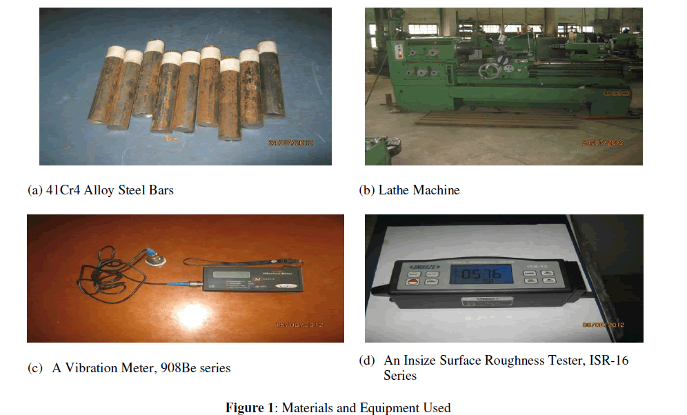
| Materials and Equipment: The work piece specimen composition test was carried out at standard organization of Nigeria, Emene-Enugu, Enugu State, to provide detailed information on the material used. Materials and equipment used in the experimental procedure of this investigation are, the work piece material type 41Cr4 alloy steel round bar of 25Ø x 150 mm with the following specifications: (UTS = 902.83 N/mmm2, BHN = 278.55 and Chemical composition of 0.4%C, 0.25 S,0.65 Mn, 1.0 Cr) (Fig 1a); lathe machine with carbide (F30 Type) cutting tool of the dimension (25 x 25 x 12.5mm) type (HSS-718) with the following angles: back and side rake angle is 10º, 12º respectively, side relief angle is 5º and side cutting edge angle is 15º, using the standard angles as given in Jaton N. W. [19] (Fig 1b); A Vibration Meter 908Be series type measurement devise (Fig 1c); and An Insize Surface Roughness Tester, ISR-16 type instrument (Fig 1d). |
 |
| Induced Machining Vibration: Self-excited vibration or self- induced vibration, which is also known as chatter, is the basis under consideration which is caused by the interaction of the chip removal process and the structure of the machine tool, that results in disturbances in the cutting zone. Chatter always indicates defects on the machined surface; vibration especially self-excited vibration is associated with the machined surface roughness. A Vibration Meter 908Be series type measurement device (Fig 1c) was used for measuring the amplitude and velocity of a point on the cutting tool. The tool vibration level was measured using a vertical data of a transducer mounted near to the tip and connected to the devices. The data include a displacement and velocity of the indicated point on the tool for each sample. The acceleration was calculated by using general equation between the amplitude and acceleration. |
| Work Surface Roughness: An inside surface Roughness tester, ISR-16 type instrument (Fig 1d) was used for the measurement of surface roughness. Three different positions for each sample at 120º with each other and the average of the three reading are considered as surface texture of the turned surface. |
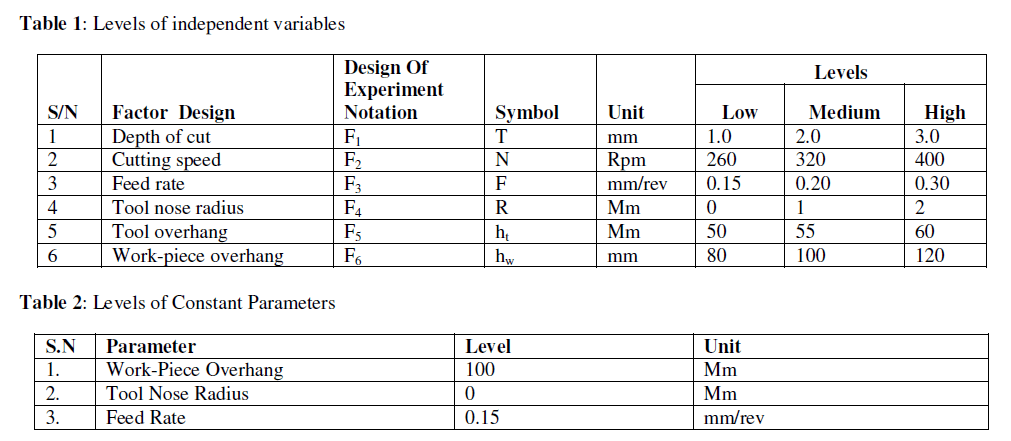
| Response Surface Method: A third-order composite factorial design was chosen, so that different interactions between independent variables could be effectively investigated. The independent variables in the study are depth of cut, cutting speed and the tool length or overhang. The dependent variables are the resulting first cut surface finish and the acceleration in both radial and feed directions. The levels of the independent variables are as shown in Table (1) whereas those of the constant parameters are given in Table 2. These levels were selected in order to cover the normal range of lathe cutting operations for an alloy steel. In order to minimize the effect of tool wear, which could affect the surface roughness quality, the tool was changed after 4 cuts. The newly installed tool was run for a few machining times to eliminate rapid tool wear. |
 |
III. RESULTS AND DISCUSSION |
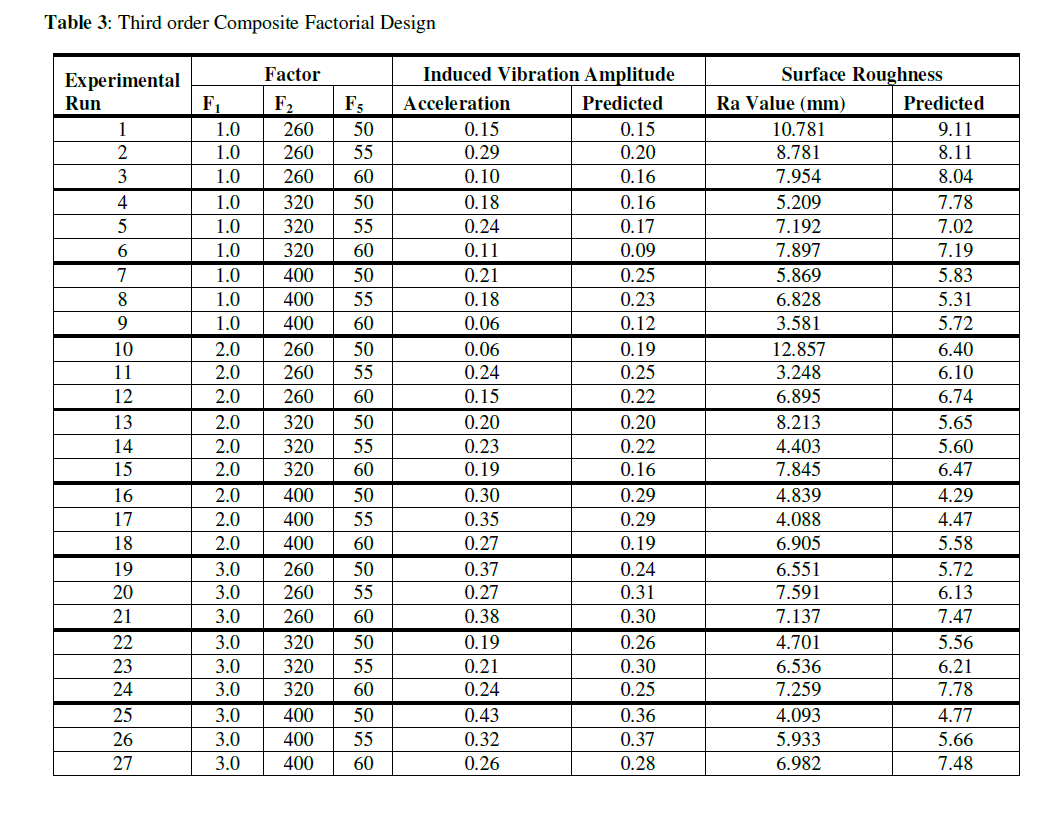
| The induced vibration amplitude and surface quality data obtained using Response Surface Methodology of the Third Order Composite Factorial Design are given in Table 3. The design of experiment took into consideration 27 experimental runs consisting of three (3) levels (low, medium, high) of the following independent variables: Depth of cut F1 (1.0, 2.0, 3.0mm), cutting speed F2 (260, 320, 400 rpm), tool overhanging F5 (50, 55, 60mm) (Table 1) while feed rate F3 (0.15 , 0.20, 0.30mm/rev), tool nose radius F4 (0, 1, 2 mm), and work piece overhang F6 (80, 100, 120mm) were kept constant (Table 2), to produce different response surface data as shown in Table (3). Analysis of the data gave rise to the prediction equations for induced vibration and surface roughness given, respectively, as: |
 |
 |
 |
 |
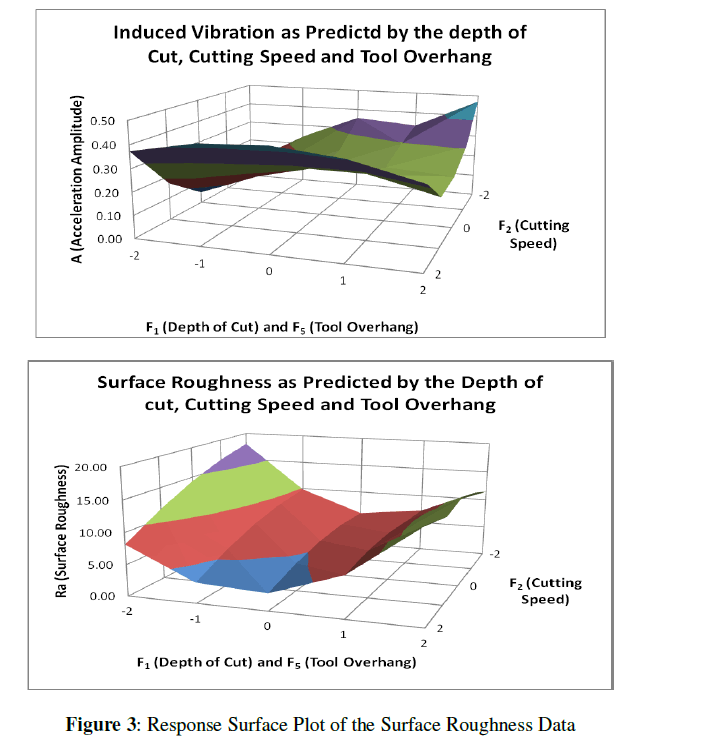
| Also, it gave rise to response surface plots for induced vibration and surface roughness as given respectively in Figs 2 and 3, which shows the relationship between depth of cut, tool overhang and cutting speed with acceleration amplitude and the surface roughness of work piece for cutting condition. The actual amplitude of the relative vibrations between tool and work piece can be measured using a displacement sensor. Figures 2 and 3 have been constructed to illustrate the main effect of induced vibration on surface roughness of work piece. It is clear that the acceleration of cutting tool has significant effect on the surface roughness of work piece. It was observed that increasing the acceleration of cutting tool through increasing the tool overhang will cause the increase in surface roughness of work piece. It also shows that the surface roughness of work piece is directly proportional to the cutting tool acceleration. From the experimental results the vibrations increase, and then, decrease with increasing in the cutting speed. The factors which lead to increasing the vibrations, such as cutting speed, and depth of cut, affect surface roughness. The more the tools overhang from the tool holder, the smaller the cross sectional dimensions of the cutting tool, and the lower the rigidity of the machine operation system, the greater the vibration of the cutting tool. Therefore, vibration, especially self-excited vibration, is associated with the machined surface roughness. Attempts have been made to use vibration signals in predicting surface quality of product from lathe machine operation using response surface methodology RSM. |
IV. CONCLUSION |
| In this paper we considered induced vibrations and surface roughness of a tool-work piece system in a turning process induced by random disturbances, and their effect on a product surface. The surface roughness of machined parts is predicted by using the response surface methodology. From the study, it is shown that, induced vibration has a significant effect on surface roughness of work piece. The surface roughness of work piece is proportional to cutting tool acceleration. This effect interacts with other independent variables such as depth of cut, cutting speed and cutting tool overhang. |
References |
|