ISSN ONLINE(2319-8753)PRINT(2347-6710)
ISSN ONLINE(2319-8753)PRINT(2347-6710)
| Remya Varghese, Manu Jayakumar M.Tech Scholar, School of Aeronautical Engineering, Hindustan University, Chennai, Tamil Nadu, India |
| Related article at Pubmed, Scholar Google |
Visit for more related articles at International Journal of Innovative Research in Science, Engineering and Technology
Discontinuities are common in airframe structure. These lead to the emergence of stress concentration regions. This turns deliberately pronounced when airframe structure experiences fluctuating loads during flight. These elevated tensile stress locations undergoing fluctuating loads may lead to fatigue cracks. In case of situations where these cracks are unnoticed they could lead to catastrophic failure of the structure. So it is highly pertinent to involve in the stress analysis of a segment of the fuselage with multiple cut-outs and fatigue damage calculation due to fluctuating pressurization loads. The fatigue damage calculation requires constant amplitude S-N data for various stress ratios and local stress history at the stress concentration. Fatigue life prediction methodologies through damage calculation are empirical in nature and therefore require test validation. Here CATIA software is used for the modelling, MSC PATRAN is used for meshing the fuselage panel and stress analysis is carried out using MSC NASTRAN.
Keywords |
| Fatigue, fuselage panel, stress concentration, stress analysis. |
INTRODUCTION |
| The aerospace industry, since it attained completeness as a separate industry is always subjected to numerous challenges. These unidentified problems which emerged long back turned more pronounced when much attention is laid upon the performance and design criteria. Several researches and experimentations are going on to tackle down and reduce the impact of these undesirable phenomena on aircrafts and other flying vehicles. It is always a matter of interest to revert attention to one of these undesirable damage or failure inducers. Fatigue is a usual and frequent mode of failure that occurs in a component subjected to alternate and repeating loads. In general, it is the weakening of a material caused by repeatedly applied loads. Also it is the progressive and localized structural damage that occurs when a material is subjected to cyclic loading. The nominal maximum stress values that cause such damage may be much less than the strength of the material typically quoted as much less than the strength of the material typically quoted as the ultimate tensile stress limit, or the yield stress limit. Fatigue occurs when a material is subjected to repeated loading and unloading. If the loads are above a certain threshold, microscopic cracks will begin to form and leads to failure [1]. This undesirable event occurs based on the stress involved and the number of load cycles [3]. The fatigue varies on its nature as high cycle, low cycle and very high cycle based on this [5]. A drastic change can be noticed in the failure life when any stress concentration factors are present in the structure [2],[9]. The elevated stress in these regions can be found using suitable finite element techniques and related softwares [4],[17]. |
| The aircraft fuselage is composed of stressed skin, circumferential bulkheads and longitudinal stringers. The skin is connected to bulkheads and stringers mostly by rivets. Fuselage is associated with a considerable number of riveted joints and is subjected to differential internal pressurization. When the fuselage is frequently pressurized and depressurized during each takeoff and landing cycle of aircraft, the metal skin of fuselage expands and contracts resulting in metal fatigue [6],[11],[18]. Fatigue damage accumulatesduring every cycle of loading in the airframe structure during its operation. The requirement for weight reduction in airframe has led to increase in the use of aluminium castings [10]. It is primarily due to the high strength-to-weight ratio associated. When the weight considerations are being fulfilled by these light metals, on the other hand it fails under repeated pressurization loads [8]. This fatigue cracks developed thereby is mainly due to intense hoop stress. Cabin pressure results in radial growth of the skin and this radial growth is resisted by frames and stringers giving local bending along the fastener lines. Fuselage skin panels are curved and these panels are under biaxial tension loading due to cabin pressure. The service life of components is estimated based upon the damage estimation occurring on it with respect to the flying environment [7],[12]. |
GEOMETRIC CONFIGURATION |
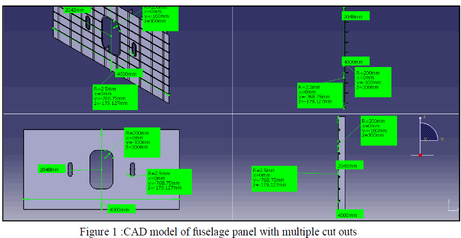
| The geometric modelling of the fuselage with multiple cut-outs indicating bulkheads, stiffeners and rivets are carried out by using Catia. The cut-outs mentioned here refers to the openings for door and windows. The bulkheads serve to maintain the required external contour at the region and they provide rigidity and strength to the structure. For purposes of stabilizing the skin there are a multiplicity of stiffeners arranged orthogonally relative to one another. The stiffeners form a multiplicity of intersection regions, which in particular when using a differential form of construction represent weak points. Furthermore, as a result of their orthogonal arrangement relative to one another the stiffeners are not optimally orientated in terms of loading.. The Catia model representing the respective region is shown in figure 1. The view associated with all mentioned components are presented clearly with dimensions indicated. The tilt and front views are also given separately in figure.1. |
 |
MATERIAL SPECIFICATION |
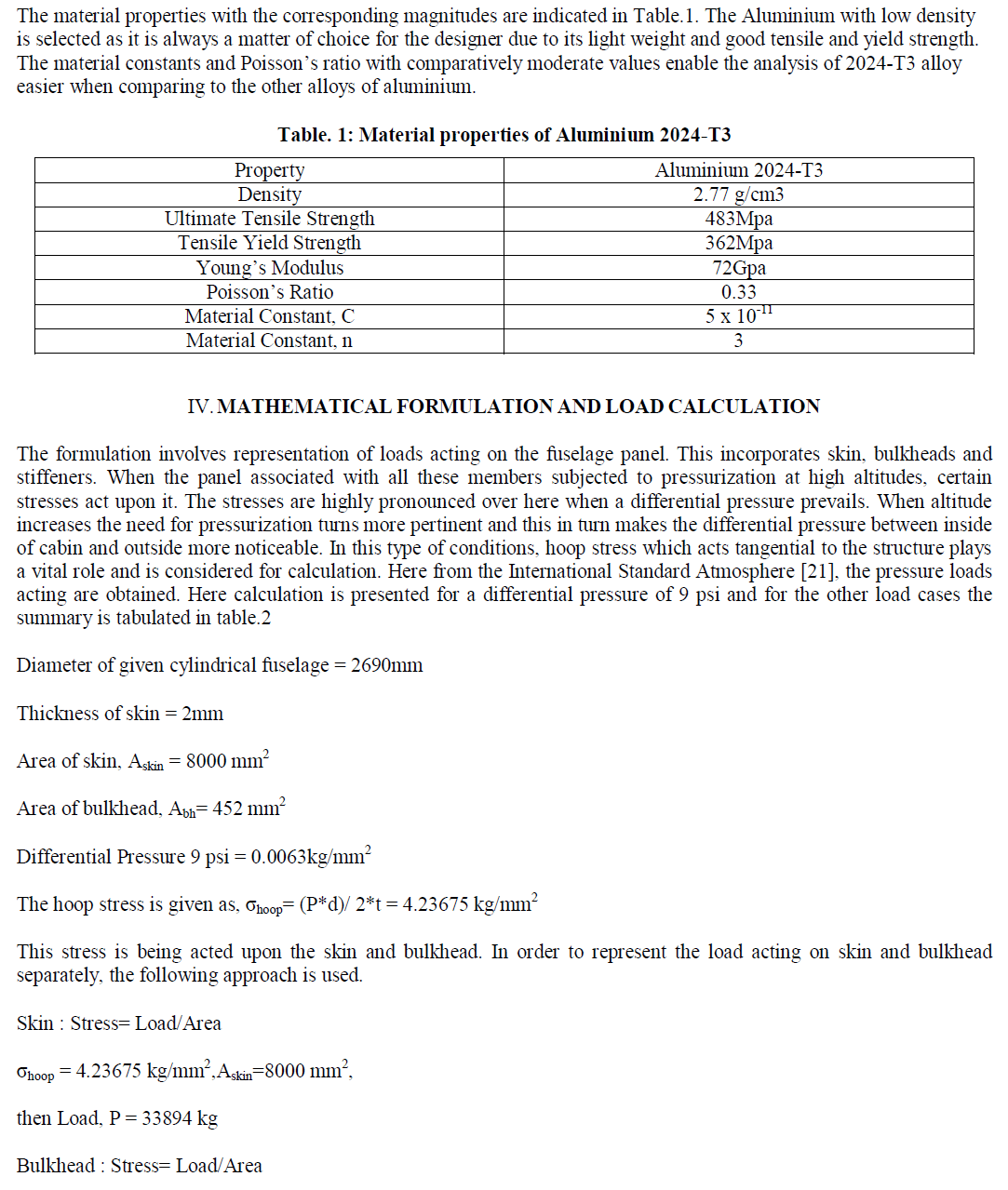
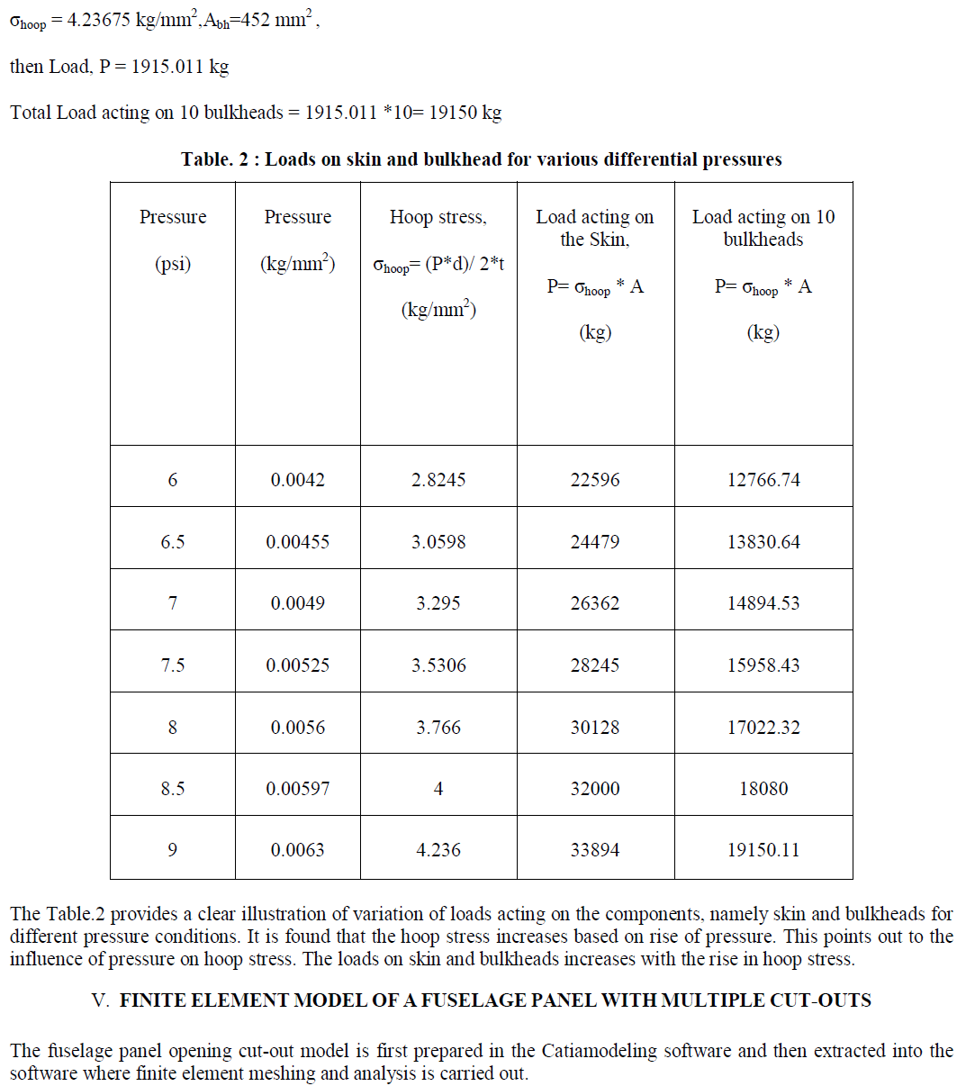
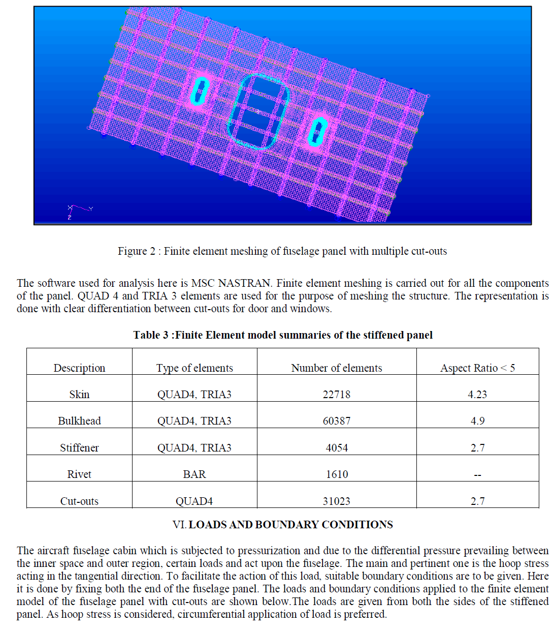
| It should be really meticulous while selecting a material for a specific part of an aircraft. The selected material should mandatorily follow all the design guidelines and comply with the pertinent performance parameters. Weight and cost considerations coupled with the following features paved Aluminium 2024-T3 as the suitable material. |
| Density |
| Young’s modulus |
| Fatigue strength |
| Ultimate and Yield strength |
| Corrosion |
 |
 |
 |
 |
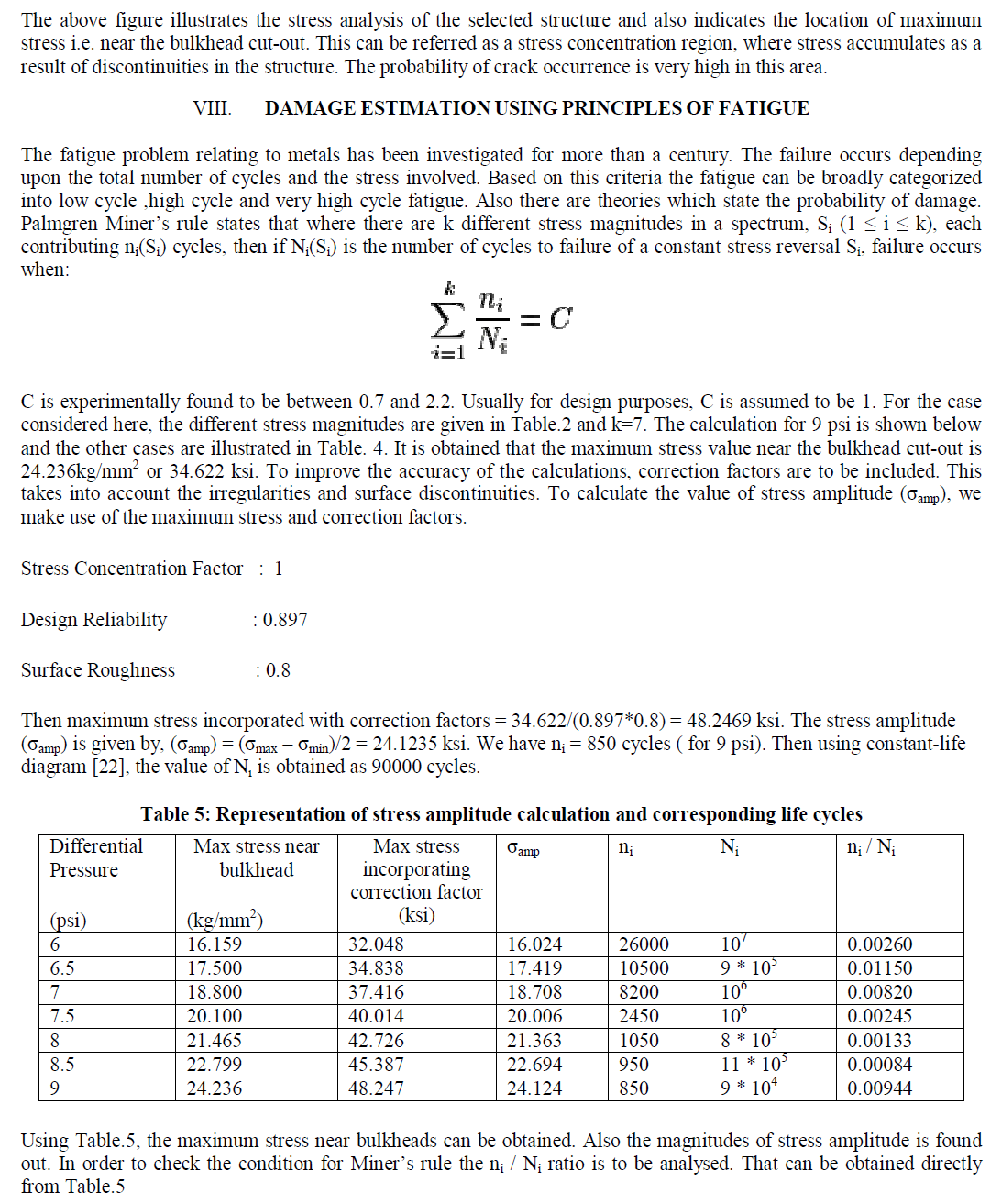 |
| Then, Σ( ni / Ni ) = 0.03637 |
| According to Miner’s rule the design is safe if Σ(ni / Ni) <1. The condition is valid here and the material is safer to operate in the conditions selected for study. |
CONCLUSIONS |
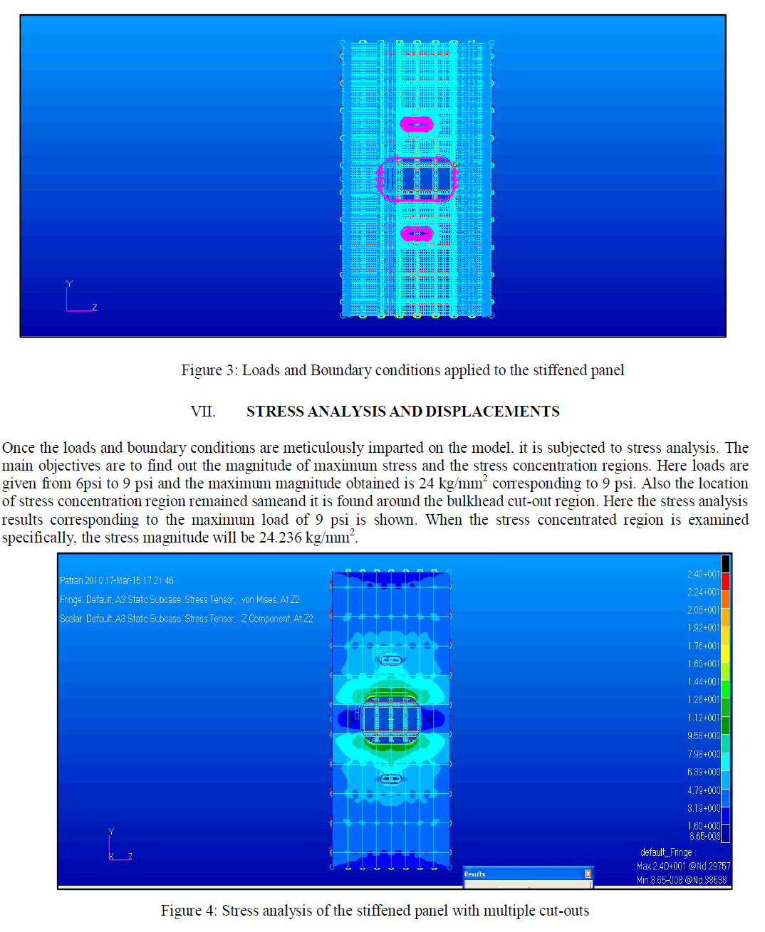
| The study conducted here based on the fuselage panel with multiple cut-outs enabled to locate the region where stress is concentrated. This is found near the bulkhead cut-outs and the magnitude of maximum stress is 24.236 kg/mm2. |
| The damage estimation is done hereafter to investigate the structure is safe under the prevailing load conditions and cycles. It has been validated that the selected fuselage panel can accommodate the impact of load spectrum considered here. |
| Also a weight optimization is done so as to analyze the load baring capacity of a thinner panel. This has been validated by reducing the panel thickness from 2mm to 1mm keeping all other criterias and parameters same. |
References |
|