International Journal of Innovative Research in Science, Engineering and Technology
ISSN ONLINE(2319-8753)PRINT(2347-6710)
ISSN ONLINE(2319-8753)PRINT(2347-6710)
K.Gobivel1, Y. Allwin Roy1, K.S.Vijaysekar2, S.Suresh Kumar2
|
| Related article at Pubmed, Scholar Google |
Visit for more related articles at International Journal of Innovative Research in Science, Engineering and Technology
Finite element (FE) analysis is used in many critical applications such as aerospace, biomedical sectors to simulate the material behavior before being manufactured. These industries are using composite materials extensively due to their inherent properties such as high strength to weight ratio, corrosion resistant and durability. Hence FE studies are imperative in understanding the material deformation characteristics of these lightweight materials. In this study it is proposed to model the carbon fiber reinforced epoxy tube material in an orthogonal turning process using 2D FE models in ABAQUS software. The FE simulations are carried out and the deformation characteristics and stress patterns of the composite tube are analyzed.
Keywords |
| Composite materials, Finite element analysis, ABAQUS, orthogonal turning. |
INTRODUCTION |
| The machining of composites is a complex and difficult process due to their unique composition and structure which is inhomogeneous and anisotropic. These materials are vital for the automobile and aerospace industries where high strength to weight ratio, oxidation and corrosion resistance are requisite properties. However, poor machinability continues to plague the industry where the need to cost ratio drives changes. In order for carbon fiber-epoxy composite materials to be used in aircraft structures accurate surfaces for bearing mounting or adhesive joints must be provided, which requires precise machining [1]. Many researchers have conducted experiments on composite materials with good results [2, 3]. |
| Arola and Ramulu [4] conducted the first study on orthogonal cutting of unidirectional graphite with epoxy to predict the cutting forces. Mahdi and Zhang [5] developed the constitutive model of a homogeneous anisotropic elastic material under plane deformation. Nayak et al [6] described the two major types of modelling approach called macro and micro mechanical models. (i) Macro mechanical models in which the composite material is generally modelled as an Equivalent Orthotropic Homogeneous Material and, (ii) micro mechanical [7] models in which the fibers are distinguished from the matrix and needs complex modelling of the fiber-matrix interface. Ali Mkadeem et al [8] conducted FE analysis of a macro-mechanical model during orthogonal machining of UD-GFRP material and analyzed the chip formation and chip breakage mode. Santiuste et al [9] focused on machining and modelling of long fiber composites for aeronautical components in GFRP and CFRP materials. Calzada et al [10] investigated the modelling and interpretation of failure mechanisms in CFRP composites and described the chip length machining forces for microstructures with fibers orientated at 0âÃâæ, 45âÃâæ, 90âÃâæ, and 135âÃâæ. Dandekar and shin [11] provided a comprehensive review on machining and modelling of composites. |
| The main objective of this study is to develop a 2D FE model to simulate the chip formation in orthogonal cutting of UD-CFRP. The modeling was done with a macro mechanical approach in which the work material was considered as Equivalent Homogeneous Orthotropic single phase material. The composite failure criteria proposed by hashin with four failure modes: fiber tensile failure, fiber compressive failure, matrix cracking, and matrix crushing, was employed in this work which clearly shows the matrix compressive damage and chip formation as like in a FRP composite. |
EXPERIMENTAL SET UP |
| The UD – CFRP/Epoxy work material was prepared by filament winding technique. The CFRP tube dimension was 55 mm (O/D) with 5 mm thickness and the fiber orientations chosen was 90º. The machining was carried out using a precision lathe and the cutting tool used for this experiment was TiAlN, with a rake angle of 5º, clearance angle of 5º and edge radius of 50μm. A Four arm strain gauge dynamometer (IEICOS) was used to measure the cutting forces. The process parameters followed during experiments were depth of cut 0.5mm, cutting speed in the range of 20-75 m/min and the feed in the range of 0.05- 0.15mm/rev. |
FINITE ELEMENT MODELLING |
| Finite element modelling was developed using the commercial software ABAQUS / EXPLICIT V6.13. The material model was considered as equivalent homogeneous orthotropic material where the individual fiber and matrix properties were replaced with EHM property. |
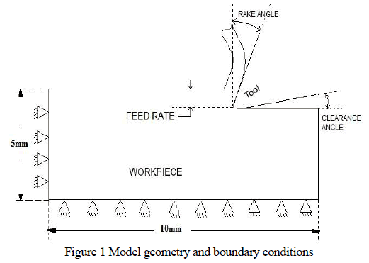
| The work material was considered as deformable and the tool was considered as rigid. The orthogonal cutting condition was made as plane stress problem to analyze the deformation patterns. Material geometry and boundary conditions are shown in fig 1. The displacement of the work piece was restrained in cutting direction and its perpendicular direction. Also the left extreme of the work piece was restrained in cutting direction. |
| A dynamic/explicit analysis was done with S4R: A4 node doubly curved thin shell, reduced integration, hourglass control and finite membrane strain. The cutting parameters and the tool geometry (cutting speed, feed, and depth of cut, rake angle and clearance angle) were defined with those used as in experimental conditions. The interaction between the tool and the work material was surface to node contact. The cutting tool was moved to work material in negative x direction by displacement boundary conditions. A predefined ramp scaling function was used by give the time/frequency and amplitude to simulate the cutting tool towards the work piece. So the nominal depth of cut is 0.5mm. Friction plays an important role during machining of any metallic and FRP material. Friction between the tool and work material was considered as columbic in nature and the coefficient of friction is 0.3. |
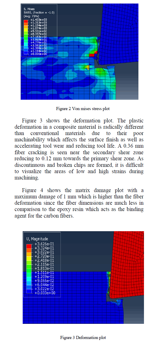
 |
 |
RESULTS AND DISCUSSIONS |
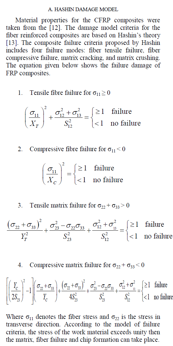
| Figure 2 shows the von mises stress plot with CFRP machining. The material was modelled as a unidirectional fiber with orientation of 90 degrees. A maximum stress of 1433 MPa is observed near the shear zone with fiber cracking at the line of contact with the tool. The stress values around the tool- work contact area are higher while the values taper off in the tertiary shear zones and other areas. However, the impact of machining forces are felt at areas away from the contact region given the anisotropic behaviour of the composite fiber which does not exhibit chip formation seen in ductile materials where a continuous chip is formed. |
 |
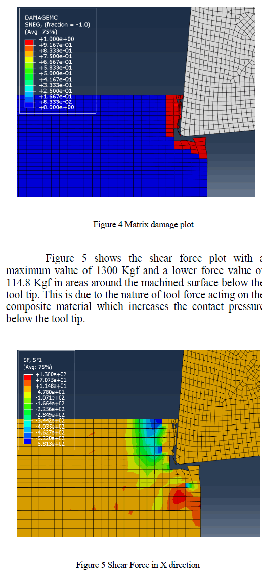 |
CONCLUSIONS |
| The finite element simulations for CFRP tube machining were carried out using ABAQUS software using an EHM methodology to model and study the chip formation. The FE model was successfully built using Hashin damage criteria and was able to simulate the stress, deformation and fiber and matrix damages reasonably well. Further studies on cutting forces and 3D modelling using Tsai Hill criteria is being explored to widen the scope of investigations of the present research work. |
ACKNOWLEDGMENT |
| The authors are indebted to AICTE (All India Council for Technical Education) for the financial support for this work. |
References |
|