International Journal of Innovative Research in Science, Engineering and Technology
ISSN ONLINE(2319-8753)PRINT(2347-6710)
ISSN ONLINE(2319-8753)PRINT(2347-6710)
| Arnab Samanta, Mohammad Shahrukh B.E. Student, Department of Electronic and Design Technology (EDT), RTM Nagpur University, Nagpur, India1 2 |
| Related article at Pubmed, Scholar Google |
Visit for more related articles at International Journal of Innovative Research in Science, Engineering and Technology
In year 2000, the share of flexible PCBs (Printed Circuit Board’s) in USA’s market was only 10% of the total PCB used. In the year 2013 there was a considerable growth of 30% rise in flexible PCB producing industries. Here we have conducted two activities for our research and survey purpose. Survey on electronic shop was done for knowing their knowledge and work experience on flexible PCB & an experiment was carried out to know theeffect of water on conductivity and other physical properties of flexible and rigid (paper phenolic) PCB.
Keywords |
| PCB, Flexible PCB, Rigid PCB. |
I. INTRODUCTION |
| Pcbs are metal foil conducting pattern, usually copper, bonded to a substrate(insulating base material )for support the metal pattern serve as the conducting path for the electrical component those are assembled on the opposite side of the board component leads are fed into holes that are drilled or punched through the base material and foil. These leads are soldered to the conducting pattern to form the complete printed circuit. In simple words PCB can be defined as ‘It is a board in which circuit is design on it’. The general advantages of pcb are- They are more reliable than any “tag” board, they adapt easily to miniaturization and modular design , provide uniformity in production, virtually eliminated wiring errors, minimizes assembly and inspection time, lowers the overall costs of the system, less vulnerable to damage from vibration, compact and easier to servie, highly suited for mass production,etc. The Basic board types are -Single sided PCB and Double sided PCB (with and without plated through holes). Modern classification of pcbs are- Ultra-Thin foil PCB, Multilayer PCBs, Multiwire PCBsand Flexible PCBs. |
| Flexible PCB was originally designed as a replacement for traditional wire harnesses. Over the years, as devices have become smaller and wearable and implantable flex PCBs offer many other benefits in addition to being flexible. Now a days flexible circuits are all around us – in cell phones, cameras, and laptops – and also in us – in pacemakers, cochlear implants, and defibrillators. General definition of Flexible PCB is ‘Flexible circuit pattern printed on flexible dielectric film.’ Other definitions are ‘ A flexible circuit in its purest form is a vast array of conductors bonded to a thin dielectric film’ or ‘Flexible pcb is flexible plastic substrates (such as polyimide, PEEK or transparent conductive polyester )on which electronic devices are mounting’. |
II. LITERATURE SURVEY |
| In the 1947 Cledo Brunetti and Roger W. Curtis published an article titled "Printed Circuit Techniques" in National Bureau of Standards, issued 15 November 1947. It describeda technique of creating circuits using flexible insulating materials. It was the birth of modern form of flexible PCB. But the use of flexible PCB flourished in late 20th century as flat conductors. In year 1952‘PhotocircuitsCorporation’, in New York, started mass production of flexible PCB. As various advantages and utility of flexible PCB surfaced, its demand in marker (especially in electronic markets) also increased. In order to properly coup up with increasing demand, various industries started doing surveys on flexible PCB. Recently in August 2007, National Physical Laboratory (NPL) Electronics conducted a survey to know which type of PCB (single, double sided, multilayer, rigid or flexible) are used in an electronic assembly in different industries. In that the percentage of flexible PCB was quiet high. In another survey, Jet Propulsion Laboratory, California Institute of Technology, tried to find out rework of various industrial equipments and instruments with Flex circuit BGAs (Ball Grid Array) and other materials. |
III. LAMINATES |
| Laminate is the most important material for producing Flexible PCB. The quality of laminate determines the quality of Flexible PCB produced. A laminate can be simply defined as the product obtained by pressing layer of filler material impregnated with resign under pressure and heat. It is very important to choose proper laminate base material. The base material should cover the following qualities: Low cost, dimensional stability under mechanical and thermal stress good tear strength, good bond with copper, good electrical properties, flame retardance, punchability, low water absorption, high flexibility. Some of the laminates that possess most of the above qualities are |
| 1. Epoxy resin or glassmat |
| 2. Polyester foil |
| 3. Polyimide foil |
| 4. Teflon foil |
IV. BENEFITS/ ADVANTAGES |
| Benefits of using Flex PCBs are: |
| 1. Flexibility - the most prominent benefit. |
| ïÃâ÷ The elastic nature of the flex PCB allows placement around edges and folds. |
| ïÃâ÷ The flexible nature of the flex circuit boards are used in electronic devices that require 3 axes connections. |
| ïÃâ÷ Very little or no wiring is required that eliminates wire connection failure and increases the reliability of the device. |
| ïÃâ÷ Space and Weight Savings |
| ïÃâ÷ Flex PCBs save up to 60% of the weight and space compared to Rigid PCB or wire harness applications. |
| 2. Bending Cycles: Flex PCB use in 3D designs eliminates connectors, while the number of bending cycles can be as many as 200,000 (with standard material) |
| 3. Anti-Vibration Benefits: Added flexibility and lighter weights allow the flex circuits to absorb and reduce the impact of the vibration to itself as well as any solder joints in connections. |
| 4. Use in Harsh Environment: Flex circuits can be built with materials that are suitable to use in harsh operating environments (materials that have the following properties: waterproof, moisture proof, shock proof, high temperature oil, corrosion resistant). |
| 5. Others |
| ïÃâ÷ Flex PCBs can eliminate the need (and cost) for connectors and cables improving connection reliability and reducing assembly time, assembly cost, and overall size of the device. |
| ïÃâ÷ Flex circuits are made of layers of polyimide instead of FR-4 (fiberglass reinforced epoxy laminate), making the board much lighter. |
| ïÃâ÷ The polyimide layers are also thinner allowing the board size to be thinner than typical rigid PCBs. |
V. DISADVANTAGES |
| 1. Not suitable for high frequency applications |
| 2. One-time initial costs are high |
| 3. Difficult changes and fixes |
| 4. Improper operation fragile |
| 5. Mishandling causes damage to the circuit. Need trained personnel to operate and soldering |
VI. APPLICATIONS |
| 1. Military |
| 2. Aerospace applications |
| 3. Computers |
| 4. Consumer electronics |
| 5. Automotive applications |
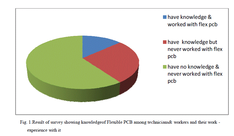
VII. SURVEY |
| Survey on fifteen electronic shops was done (survey date: 13th Jan 2014. City: Nagpur). For this direct communication was done with the shopkeepers and their technicians. |
| From the survey it was found out that: |
| ïÃâ÷ Only 13.33% of them have knowledge of flexible PCB and have worded with them |
| ïÃâ÷ 26.65% have some knowledge of flexible PCB but never have worked with them |
| ïÃâ÷ Remaining 60% have no knowledge of flexible PCB and never have worked with them |
 |
VIII. EXPERIMENTAL RESEARCH |
| This experiment was carried out to determine the effect of water on various parameters of flexible and rigid PCB. The material used for this purpose are: flexible(polyimide foil)and rigid (paper phenolic) pcb, multimeter, 1.5v dc power source, timer, two containers with tap water, dry cotton pulp, paper, pen,etc. |
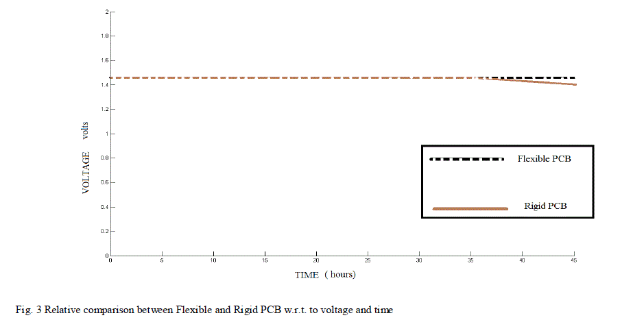 |
| The process was carried out in the following manner: Both the pcbs were immersed in container having tap water and timer was put on. After some time interval the pcbs were pulled out and soaked dried with cotton pulp. Then 1.5v dc power source was applied across the PCBs. The conductivity of the copper tracks (inner as well as outer), each having length of 3cm, was checked using multimeter. Also the thickness of the board was measured. Again the same process was repeated. The table (Fig. 2) shows the corresponding outcomes. |
IX. OBSERVATIONS |
| 1. With increase in time, the conductivity of inner as well as outer tracks of rigid pcb decreases (outer tracks at a greater rate than inner tracks ) |
 |
| Figure 3. shows the availability of voltage in tracks of both types of PCBs. After twenty eight hours there is a reduction of voltage available in tracks of rigid PCB. But still a constant voltage is obtained from the tracks of flexible PCB |
| 2. After 26 hours, there is some leakage voltage appears on some part of the insulating portion of the rigid pcb |
| 3. The above two phenomenon does not takes place in case of Flexible PCB |
X. CONCLUSIONS / FUTURE SCOPE |
| 1. The availability and knowledge of flexible pcbs in Nagpur is very limited. Also the skilled workers required to work with flexible pcbs are also very less |
| 2. In case of rigid PCB, the copper tracks become dimmer (when prolonged immersed in water) because some copper particles get washed away in water and during drying with cotton. Also the loss of conductivity of the tracks was due to the above reason. |
| 3. As flexible pcbs are made up water resistance plastic material (substrate as well as lamination and base material) and copper tracks are firmly adhere to the base material, loss of conductivity and dimmer of copper tracks does not take place even if it is kept for longer time in water of moist region. |
| 4. In case of rigid PCB, water penetrates in some portion of base as well as substrate. This may cause short circuit of the closely placed tracks (when kept in water for longer time).This is not the case with flexible pcbs. |
| 5. Hence, flexible pcbs should be used in damp and moist places and also in the critical circuits where speed and complete transfer of voltage in any environmental condition is very necessary. |
| 6. Electronic equipment made with flexible pcb can be used in Rain Forests for monitoring climatic changes or movements of animals |
| 7. As flexible pcbs have many advantages, so more number of electronics items should be designed using flexible PCB. For this proper knowledge and technical skills, required to work with flexible PCB, should be provided to the technicians and workers. |
References |
|