ISSN ONLINE(2319-8753)PRINT(2347-6710)
ISSN ONLINE(2319-8753)PRINT(2347-6710)
P. Saranya1, C. Gnanavel2
|
| Related article at Pubmed, Scholar Google |
Visit for more related articles at International Journal of Innovative Research in Science, Engineering and Technology
This paper proposes a three phase multipulse ac – ac converter with PI and FUZZY controller. The matrix converter system is competitive solution to replace the conventional two stage ac to ac converter. In this paper, a matrix converter driving a speedcontrolled induction machine is examined under openswitch fault. First, PI controller is proposed using only the motor torque and current. Second, FUZZY controller is proposed to control the motor speed. The proposed techniques do not require the additional hardware devices or circuit modifications to the matrix converter. The results of this paper show that the proposing method can maintain the motor speed with a minimum ripple content—a fivefold improvement over the uncompensated system.
Keywords |
| Reliability, Matrix Converter, Torque ripples |
INTRODUCTION |
| Recently, significant research work has been done in matrix converter (MCs) for control the induction machines (IMs).The matrix converter makes the traditional voltage source inverter (VSI) in ac motor drives using various high-performance control techniques as direct torque control. The advantageous features such as bidirectional power flow, sinusoidal input and out current, input power factor controllable. |
| The reasons for installing an input filter before the matrix converter are twofold: First step, it can mitigate the input current harmonics. Second step, it is used to assist the commutation of switching devices and to assure the normal operation of matrix converter. Since the first application of matrix converter control, the space vector modulation (SVM) is mostly used. In this paper, the purpose of SVM is to trigger pulses for bidirectional IGBT switches. A matrix converter is a single stage converter with m*n bidirectional switches and this connected to m-phase voltage source to n-phase load. In practical view, it connects a three phase source to a three phase load, typically a induction motor (ac), |
 |
| A matrix converter is a forced commutation direct frequency converter that can be directly connecting two independent multiphase voltage system together (e.g., power grid, alternating current for motor (ac)). And it can be achieve the bidirectional power flow, independent control of displacement power factor without use of bulky and limited lifetime reactive elements, such as large electrolytic capacitors or ac inductors. The matrix converter system is, to replace the conventional two-stage ac/dc/ac converter, but system reliability remains are open issue. |
| SCOPE OF THIS PAPER |
| This paper seeks to address the aforementioned problems in matrix converter. A Conventional 3 phase matrix converters driving a speed controlled Induction machine (IM) is investigated both theoretically and experimentally. First, a system description is briefly presented (Section III). In this proposed, predictive direct torque control method is used. Finally the FPGA controller is presented (Section IV). No need of extra devices is required to maintain balanced and nearly sinusoidal threephase output currents. The experimental results show the proposed method has satisfactory performance under the operating condition. |
SYSTEM CONFIGURATION |
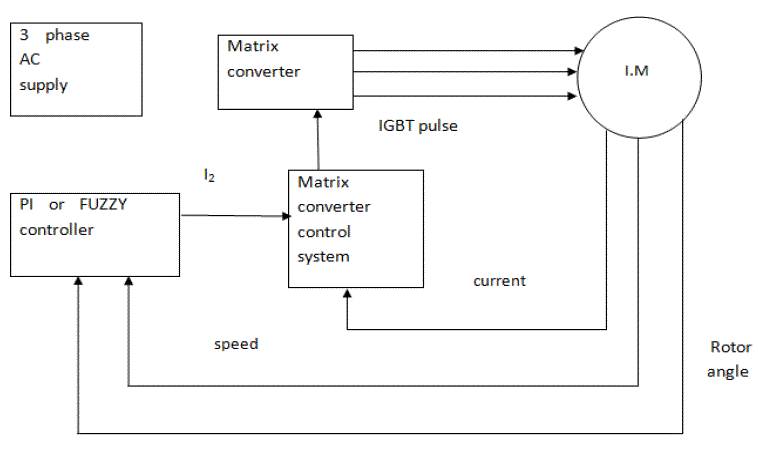
| The proposed drive system of configuration is shown in Fig. 1. The drive system hardware consists of a wye-connected Three-phase induction machine (IM) with mechanical load, a matrix converter (10-kW rating), and a FPGA system. An encoder (2500 pulses per revolution) is mounted on the motor shaft each output phase of a 3 phase matrix converter is connected to three input phases by three ac switches. When one ac switch of an output phase is an opened fault, there are two remaining ac switches that can be used to connect to the two related input phases. The two Constant torque three phase motors provide the same amount of torque regardless of the operating speed. Most remaining healthy output phases can still receive any of the possible voltage from the three input phases. In the recent years, the PI and FUZZY controller are emerging as a promising control solution for high power AC induction drives. For that reason, this project adopts the PI and FUZZY controller theory, to develop several new and competitive control methods for the doubly fed induction machine. The three phase AC induction motor is a rotating electrical machine. The conduction complexity is medium. This type of motor is very reliable and efficient at low speed. This motor is controlled by multi-phase inverter controls, which allow the motor to be set at different speeds at different moments, according to freescale. |
 |
| applications have constant torque three phase motors. The result is that the power output varies directly with speed, according to Pacific Liquid. A wound-rotor motor is a type of induction motor where the rotor windings are connected through slip rings to external resistances. Adjusting the resistance allows control of the speed/torque characteristic of the motor. Wound-rotor motors can be started with low inrush current, by inserting high resistance into the rotor Compared to a squirrel-cage rotor, the rotor of the slip ring motor has more winding turns; the induced voltage is then higher, and the current lower, than for a squirrel-cage rotor This article compares the response of a induction circuit; as the motor accelerates, the resistance can be decreased. Speed control can be accomplished without sensors, as opposed to other kinds of motors. This motor can have very low cost in relation to the amount of horsepower that it gets. The torque power of this motor when first started is higher than other motors machine with scalar speed PI controls and with Fuzzy logic controls. The simulation has been developed using Simulink and Mat lab. The operation of the motor has been verified with different speed targets in form of steps. |
SIMULATION CIRCUIT FOR MATRIX CONVERTER CONTROL SYSTEM |
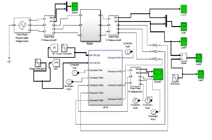
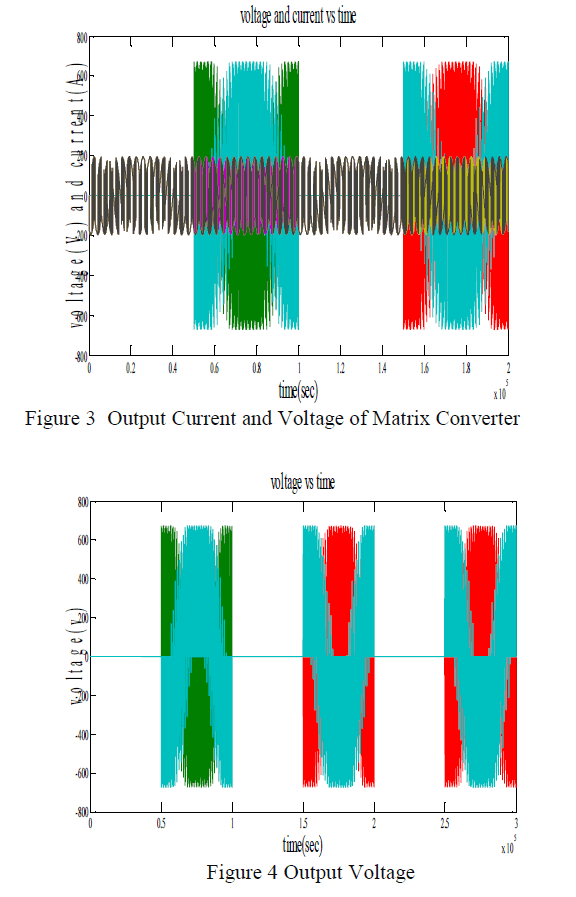
| The input of voltage and current are given to matrix converter below. And the output voltage and current of matrix converter also have shown in graph. |
| The sampling rate has to be set much higher than both input and output frequencies, and the duration of each sample is controlled in such a way that the average value of the output waveform within each sample period tracks the desired output waveform. |
 |
| If the switching frequency of the matrix converter is set to a value that is much higher than the input and output frequency, the input currents drawn by the converter are sinusoidal in figure 3. |
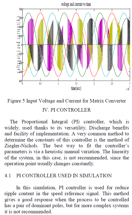
| The matrix converter performance in terms of input currents represents a significant Improvement with respect to the input currents drawn by a traditional VSI converter with a diode bridge rectifier, whose harmonic spectrum shows a high content of low-order harmonics. Under this constraint in figure 4, the maximum output voltage the matrix converter can generate without entering the overmodulation range is equal to v3/2 of the maximum input voltage: this is an intrinsic limit of matrix converter and it holds for any control law. |
| The matrix converter performance in terms of input currents represents a significant Improvement with respect to the input currents drawn by a traditional VSI converter with a diode bridge rectifier, whose harmonic spectrum shows a high content of low-order harmonics. Since no energy storage components are present between the input and output sides of the Matrix converter, the output voltages have to be generated directly from the input voltages in figure 5. |
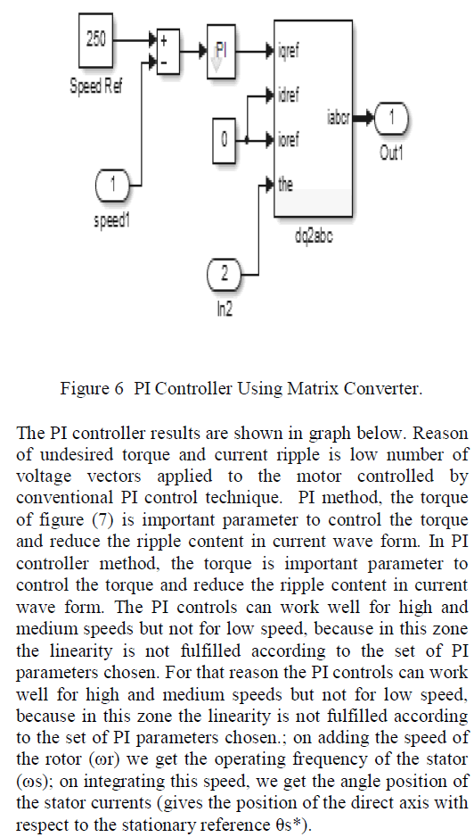
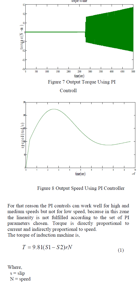
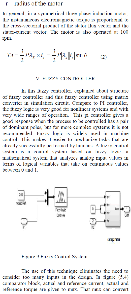
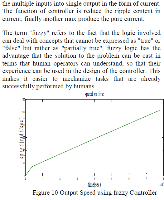
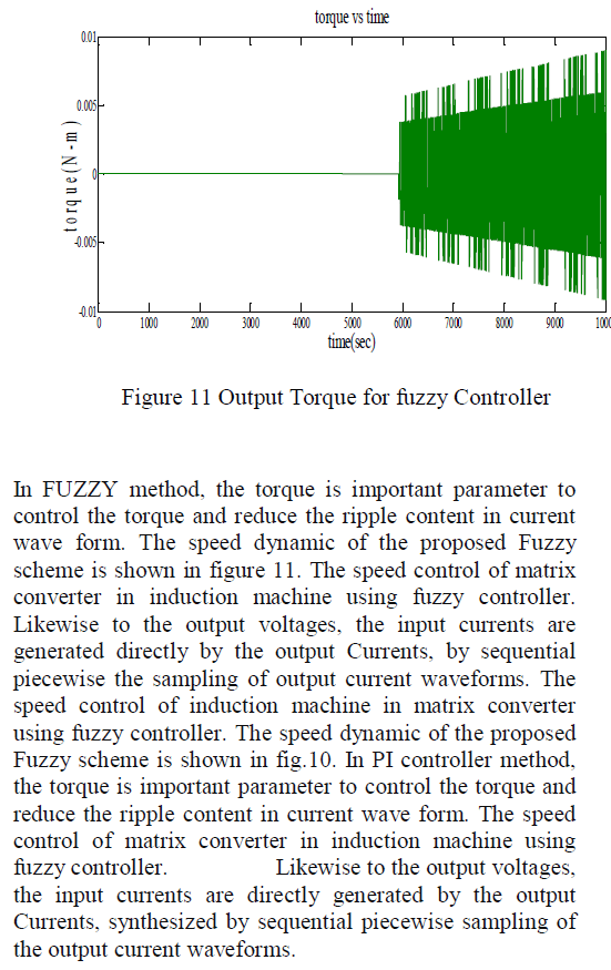
| Reason of undesired torque and current ripple is low number of voltage vectors applied to the motor controlled by PI control technique. This PI control method is a speed control of matrix converter fed by an induction machine. The matrix converter performance in terms of input currents represents a significant Improvement with respect to the input currents drawn by a traditional VSI converter with a diode bridge rectifier, whose harmonic spectrum shows a high content of low-order harmonics. But in PI controller the torque pulsation is very high. SVM techniques have several advantages that are offering better DC bus utilization, lower torque ripple, lower total harmonic distortion in the AC motor current, lower switching loss, and easier to implement in the digital systems. Result shows that the torque, flux linkage and stator current ripple are decreased with the improved controller technique. Compare to PI controller, the fuzzy logic is very good for nonlinear systems and with very wide ranges of operation. Induction motors generally will have low starting torque compared to dc series motor. Slip ring induction motor have big advantage of having high starting torque compared to squirrel cage motor. |
| Therefore slip ring induction motors are generally employed where load requires high starting torque or good speed control. They are employed in hoists, elevators, compressors, printing presses, large ventilating fans, loads requiring speed control such as for driving lifts and pumps. |
 |
 |
 |
 |
 |
 |
 |
SIMULATION CIRCUIT FOR MATRIX CONVETER |
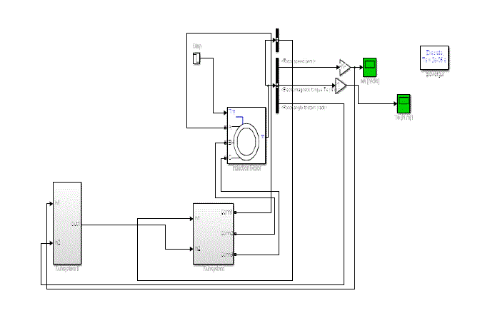 |
| Figure 12 Simulations for Matrix Converter |
| Simulink is an environment for multi domain simulation and Model-Based Design for dynamic and embedded systems. It provides an interactive graphical environment and a customizable set of block libraries that let it design, simulate, implement, and test a variety of time-varying systems, including communications, controls, signal processing, video processing, and image processing. Fuzzy logic is widely used in machine control. In this simulation circuit, fuzzy controller is used to control motor. This article compares the response of an induction machine with speed PI controls and with Fuzzy logic controls. The operation of the motor has been verified with different speed targets in form of steps. |
| Squirrel Cage Induction Motors are widely used in Industrial applications than slip ring induction motors due to cheaper in cost, rugged in construction, low maintenance. Squirrel Cage Induction Motors are suitable for applications where the drive requires constant speed, low starting torque and no speed control drives. Induction motors generally will have low starting torque compared to dc series motor. Slip ring induction motor have big advantage of having high starting torque compared to squirrel cage motor. |
| Therefore slip ring induction motors are generally employed where load requires high starting torque or good speed control. They are employed in hoists, elevators, compressors, printing presses, large ventilating fans, loads requiring speed control such as for driving lifts and pumps. Squirrel cage induction motors are widely used in industries. Almost 70% of the industrial motors and drives comes under these category. In Squirrel cage induction motors, rotor windings wound in squirrel cage. These motors are very robust in construction and very cheap. These motors can operate at any working conditions. Some of the advantages, disadvantages and applications of squirrel cage induction motor compared with slip-ring induction motor.A wound-rotor motor is a type of induction motor where the rotor windings are connected through slip rings to external resistances. Adjusting the resistance allows control of the speed/torque characteristic of the motor. Wound-rotor motors can be started with low inrush current, by inserting high resistance into the rotor circuit; as the motor accelerates, the resistance can be decreased. Compared to a squirrel-cage rotor, the rotor of the slip ring motor has more winding turns; the induced voltage is then higher, and the current lower, than for a squirrel-cage rotor. Initial and maintenance cost is more compared to squirrel cage motor because presence of slip rings, brushes, short circuiting devices etc. Speed regulation is poor when operated with external resistances in rotor circuit Efficiency and power factor of slip ring motor is lower compared to squirrel cage induction motor |
CONCLUSION |
| This paper presents a torque and speed control of matrix converter fed by an induction machine. This paper mainly contributed on torque and speed controlled using PI and FUZZY controller. In this induction machine, the squirrel cage induction machine is used. The main drawback of fuzzy controller, it’s settling time will be high compare to PI control. This article compares the response of an induction machine with speed PI controls and with Fuzzy logic controls. This PI controller method gives a good response when the process to be controlled has a pair of dominant poles, but for more complex systems it is not recommended. |
References |
|