ISSN ONLINE(2319-8753)PRINT(2347-6710)
ISSN ONLINE(2319-8753)PRINT(2347-6710)
Nataraj R1 , Ms .T.Sheela2, Dr .T Muthumanickam3, S.Kalaivani4
|
| Related article at Pubmed, Scholar Google |
Visit for more related articles at International Journal of Innovative Research in Science, Engineering and Technology
This paper summarizes Media-converter is a networking device that makes it possible to connect two dissimilar media types such as copper to fiber optic cable with OAM feature (Operation Administration and Maintenance).Media Converters are used in MAN access network (metropolitan area network) and data transport services to enterprise customers and Fiber to the Home (FTTH) for broadband access for last-mile solution, mainly for end users. The OAM media converter is implemented using the chipsets of PIC and Broadcom, explained in detail. The main benefit of the proposed OAM feature is its simplicity, compact and low cost design. Finally, a media converter with an OAM feature was built and is currently in the process of testing.
Keywords |
| Operation Administration and Management (OAM); Field Programmable Gate Array (FPGA); Ethernet |
INTRODUCTION |
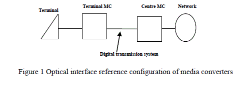
| A media converter is a simple and inexpensive networking solution device that makes it possible to connect two dissimilar media types like conversion of copper media to fiber media. and fiber to copper media. They are important in converting copper port to an Optical port with an SC connector. The use of fiber optics is advisable when reliability demands are high or there are long distances to cover. They are also used in metropolitan area network (MAN) access and data transport services to enterprise customers. Media converter types range from small standalone devices high and PC card converters to port-density chassis systems that offer many networking features like fiber link status and copper link status. On some devices, Simple Network Management (SNMP) enables proactive management of copper and fiber link statistics and sending traps to network managers in the event of a copper or fiber break status, monitoring chassis environmental .Here the terminal machine is connected to central machine via optical fiber. The management information of the terminal machine is observed in the central machine.OAM describes optical interface and logical functions of a media converter applied for a fiber media, that has operations, administration and maintenance functionsOAM frame will have the following features which is explained in the section Conclusion and results:Fiber Path Testing Copper Path TestingPropriety info (if any)OAM is the protocol for installing, monitoring and troubleshooting Ethernet metropolitan area network (MANs) and Ethernet WANs. |
 |
SYSTEM ARCHITECTURE |
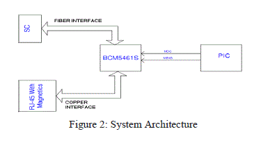 |
| The board works as an unmanaged media converter which supports 1000 Mbps speed and indentifies OAM events like copper link and fiber link. The main chipsets used are 10/100/1000 Ethernet Tran receiver and PIC Microcontroller. |
| A) HARDWARE INTERFACES |
| B) Copper Interface |
| RJ-45 with Magnetics and without LED has been used for copper interface and connected to BCM5461S. The power supply used for Magnetics Center tap is +2.5V. |
| C) Fiber Interface |
| The optical transceiver used is Hi-Optel’s This is a high performance, cost effective module, which is compliant with Gigabit Ethernet and Standard of IEEE-802.3. This transceiver operates at the normal wavelength of 1310 nm. |
| D) BCM5461S |
| Gigabit Media converter which converts Electrical signals to optical signals. This is generally a Gigabit PHY, which converts electrical signal to Optical Signal. This PHY management interface has been operated from PIC for initialization and as well as PIC gets Link related information to display FEF failures |
| E) PIC24JF64GA |
| PIC is a controller, which has been communicating with BCM5461S through 2-wire management interface for PHY initialization and to get Link failure details. PIC gets an interrupt from BCM5461S, in case of link failure and PIC has to read BCM5461S registers to analyze and display the type of failure. PIC controls Copper OK, Copper FEF, Fiber Ok, and Fiber FEF LEDs depending upon status of registers read from BCM5461S. |
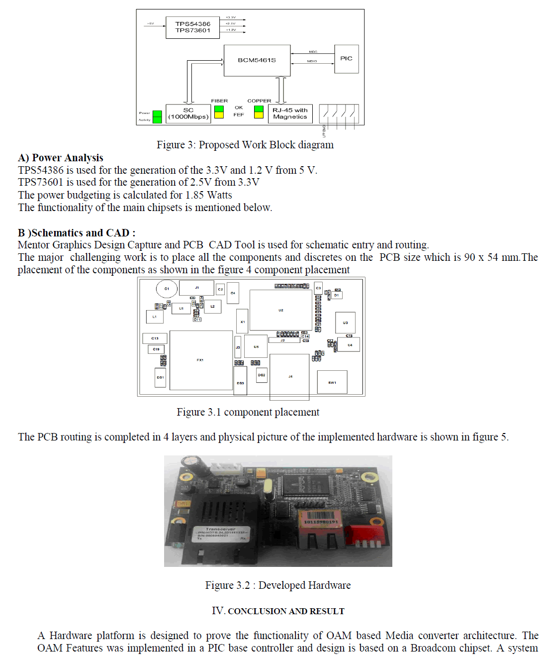
| Along with the above interface it also indicates the faulty condition on the LEDs.Below is the description. |
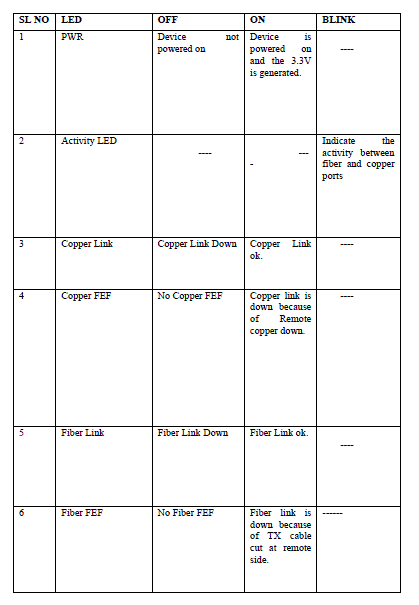
| Power on LED: To indicate power module ON |
| Activity LED: To indicate the activity between Fiber and copper port. |
| Copper OK LED: To indicate Copper Link and cable are ok. |
| Copper FEF LED: To indicate Copper Link is down and it is because of Remote Copper is down. |
| Fiber OK LED: To indicate Fiber Link and cable are ok |
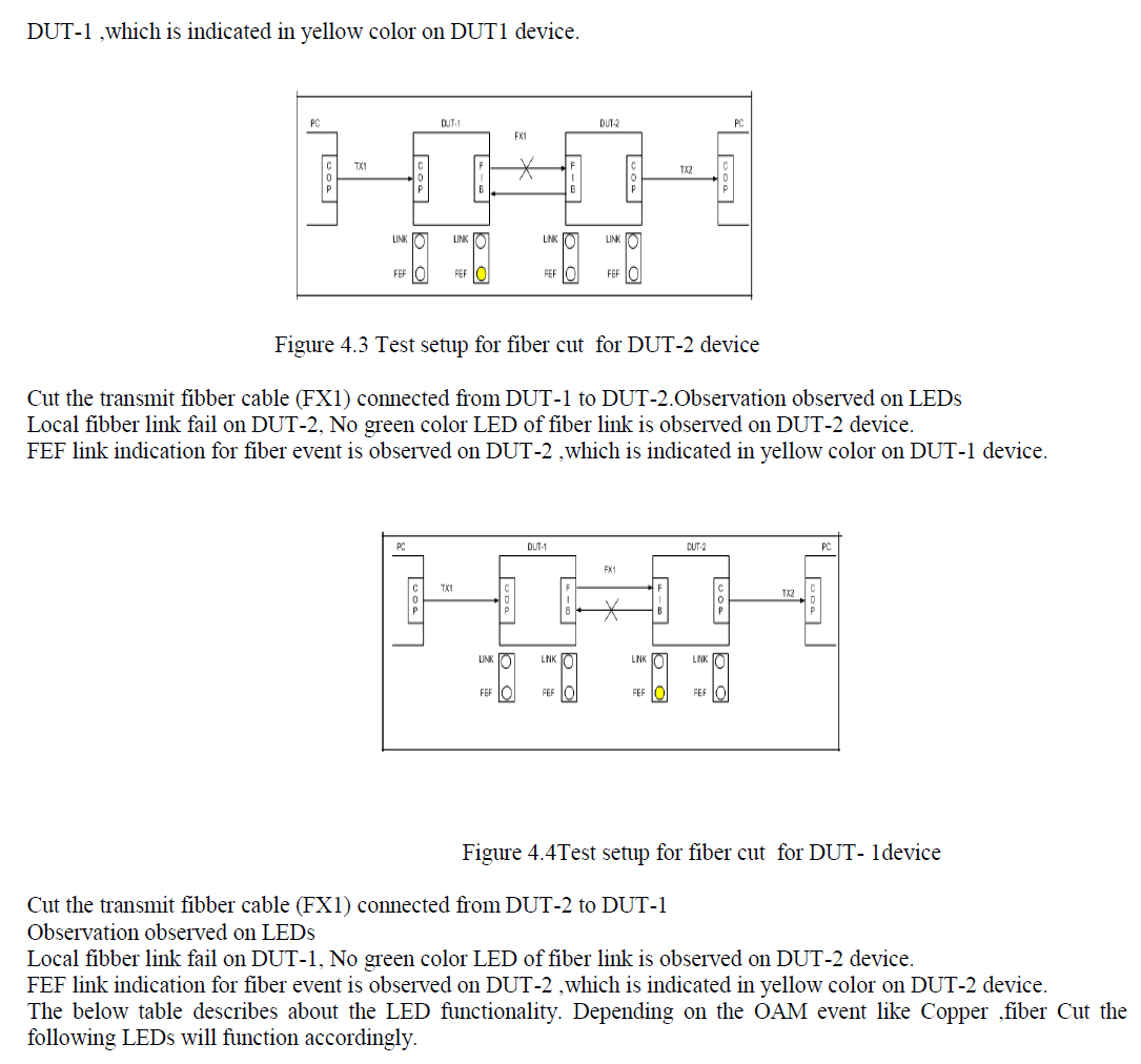
| Fiber FEF LED: To indicate Fiber link is down and its because of Fiber TX cable cut. |
METHODOLOGY |
| BLOCK DIAGRAM |
| The basic building of a design is a block diagram which is shown figure 2. It describes one gigabit copper port and one fiber port interfaced to gigabit PHY with the PIC interface for initialization |
 |
 |
 |
 |
CONCLUSION |
| In this paper, we propose a low tangling and awesome DCT change in light of the CORDIC computation is shown. The proposed CORDIC based Integer DCT building plan simply have need of 78 cuts rather than 120, number of LUT's are 110 rather than 156 and deferral has been diminished to .2ns so speed has been enhanced in ideal level. The proposed count not simply lessens the computational multifaceted design widely stood out from the first customary DCT; it in like manner keeps the considerable quality change result. In this look upon, the proposed DCT figuring is amazingly suitable for low zone and fast sign changing applications, for instance, HEVC. |
References |
|