Journal of Global Research in Computer Sciences
ISSN: 2229-371X
ISSN: 2229-371X
Rouf Ali*
Department of Computer Application, Govt Degree College Boys Sopore, Jammu and Kashmir, India
Received: 27-Jan-2022, Manuscript No. grcs-22-52244; Editor assigned: 31- Jan-2022, Pre QC No. grcs-22-52244 (PQ); Reviewed: 14- Feb-2022, QC No. grcs-22-52244; Accepted: 17-Feb-2022, Manuscript No. grcs-22-52244 (A); Published: 24-Feb-2022, DOI: 10.4172/ 2229-371X.13.1.002.
Visit for more related articles at Journal of Global Research in Computer Sciences
Sorting algorithms rearrange data items/elements of an array/data list in a certain order, either in ascending order or descending order with numerical data, alphabetically with character data and chronologically with the date data type. There are several programming applications used in computer science that apply sorting techniques. There are two types of sorting algorithms. Comparison based algorithms and non-comparison based algorithms. In a comparison-based sorting algorithm, elements of an array are compared with each other to determine which of two elements should occur first in the final sorted list. The best comparison-based sorting algorithms have a complexity lower bound of n log n. Comparison based sorting algorithms make no assumption about the input and can address any input case. Non-Comparison based algorithms use the nature of data items in the list to perform sorting. Their sorting algorithms use special information about the keys (values/items/elements) and operations other than comparison to determine the sorted order of elements. Consequently, n log n lower bound does not apply to these sorting algorithms. Non-comparison based algorithms run in linear time and requires special assumptions about the input sequence to be sorted.
Non-Comparison based algorithms use the nature of data items in the list to perform sorting. Their sorting algorithms use special information about the keys (values/items/elements) and operations other than comparison to determine the sorted order of elements. Consequently, n log n lower bound does not apply to these sorting algorithms. Non-comparison based algorithms run in linear time and requires special assumptions about the input sequence to be sorted.
Sorting is a computationally expensive and time-consuming operation that requires a lot of hardware resources. Again sorting large datasets slows down the overall execution so solutions to accelerate sorting are needed. There are different approaches to overcome these limitations. Both comparison and non-comparison based algorithms are implemented in software and require a large number of iterations and operating cycles to run on processors. These algorithms are dependent on the processor architecture for producing the sorted output. By increasing the number of input records, the execution time will be increased as well. Several sorting techniques speed up their performance by exploiting the parallelism of multicore processors or GPU (Graphic Processor Units) architectures. In recent years, designers have taken interest in designing hardware accelerators using Field-Programmable Gate Arrays (FPGAs).
In this paper, I have studied various hardware solutions for sorting. The circuitry at the processor level responsible for sorting has been identified; its role and different modifications possible to accelerate sorting have been discussed. Some application-specific circuitry has also been studied, this circuitry can be based on comparator and swap circuitry as in sorting networks or non-comparator based hardware solutions. In addition to this, the extension of the instruction set of the processors to incorporate software instructions to implement sorting has also been studied.
Sorting networks; Algorithms; Computer
Computers around the world spend around half of the computational time performing searching and sorting. A large number of applications using sorting are scientific computing image processing multimedia and network processing database operations, radio networks artificial intelligence and robotics, scheduling, data compression and scientific computing [1-15] etc. The algorithmic complexity of the sorting algorithm is written in a form known as Big-O notation, where the O represents the complexity of the algorithm and a value n represents the input size of the set. For example, O (n2) means that an algorithm has quadratic complexity.
All the comparison-based sorting algorithms use comparisons to determine the relative order of elements. e.g., insertion sort, merge sort, quick sort, heap sort. The best worst-case running time for comparison sorting is O (n log) for serial algorithms [16]. The list of well-known comparison sorts are Quick sort, Merge sort, In-place merge sort, Intro sort, Heap sort, Insertion sort, Block sort, Tim sort, Selection sort, Cube sort, Shell sort, Bubble sort, Exchange sort, Tree sort, Cycle sort, Library sort, Patience sorting, Smooth sort, Strand sort, Tournament sort, Cocktail shaker sort, Comb sort, Gnome sort and Odd-even sort.
Some of the comparison based algorithms can be implemented on parallel computing architectures and the worstcase complexity is O (n) for such parallel algorithms.
Non-comparison sorts do not use the comparison of elements to determine the order and are possible in linear time (under certain assumptions) i.e. O (n). As such, they are not limited to O (n log n). Many of them are based on the assumption that the key size is large enough that all entries have unique key values. The list of well-known Noncomparison sorts are Pigeonhole sort, Bucket sort (uniform keys), Bucket sort (integer keys), Counting sort, LSD Radix Sort, MSD Radix Sort, MSD Radix Sort (in-place), Spread sort, Burst sort, Flash sort, Postman sort.
Sample sort can be used to parallelize any of the non-comparison sorts, by efficiently distributing data into several buckets and then passing down sorting to several processors, with no need to merge as buckets are already sorted between each other.
Parallel computing can be therefore utilized possibly for speed up of sorting a whether the sorted output is achieved through comparison sort or non-comparison sort or hybrid sorting algorithm.
Each sorting algorithm has its advantages and limitations but whatever is the sorting algorithm the hardware components of the processor that is used to achieve sorted output is ALU (Arithmetic and Logic Unit). For comparison based algorithms, the main operations utilized in the sorting of data lists are comparison and swapping. Comparison operation is performed internally in processors e.g. intel 8085, 8086 series by using a digital circuit called subtractor, which is present in ALU. This Comparison is slower because it involves the execution of specialised instructions to examine the flag registers to confirm the results of the comparison. For comparison operation, a specialized digital circuit called a comparator circuit can be used for comparisons. Comparators don’t use subtraction operations (Subtractor) for comparison but have an internal logic circuitry to produce the results of comparisons.
It is well established that array data structures are contagious clocks of memory that are involved in storing input in comparison based or non-comparison based sorting. The rearrangement of array elements in unsorted array involves addressing computation of array elements to carry out read and write operations. The Digital circuits called adders and multipliers present in ALU are utilised for the computation of addresses of an array element using a starting address of the first element of the array. Digital adders can be serial or parallel and this greatly influences the speed of the addition process. Digital arithmetic circuits are also utilised in non-comparison algorithms e.g. radix sort to compute the next significant digit required at each pass this can be also achieved through arithmetic operations performed in ALU. The Design of the arithmetic circuits and comparators as well the digital technologies used to speed up the operations of these circuits has a direct relation to the sorting process.
If we observe that earlier processor generations down the timeline had a single ALU or PE (Processing Element). Nowadays processors are equipped with multiple ALUs this greatly enhance the speed of processing because multiple ALUs can be used concurrently in parallel to perform the operations needed for sorting again the different operations in ALU can be run in the pipelined fashion. To better satisfy performance requirements, fast accelerators based on FPGAs, GPUs and multi-core CPUs can be utilised [17].
From all this, it follows that the organization and architecture of ALU influence the sorting because the components of ALU adders, subtractors, and comparators are involved in the sorting process directly. Again serial or parallel processing has a major effect on the time taken for the sorting process for a given input. I observe that there is a great scope in accelerating the sorting process by developing specialized hardware for solving this problem because it is the hardware that has to carry out the sorting internally. The hardware solutions for sorting can be based on Comparator and Swap Circuitry (CAS) or non-comparison based hardware. The processor instruction set can be also extended to incorporate specialized instructions.
Hardware-based solutions for sorting
The hardware solutions can be classified into those solutions which use digital circuits called comparators circuits to accelerate sorting or the circuits that do not use comparators.
Comparator and Swap (CAS) circuit based hardware solutions: A hardware solution called comparator networks or sorting networks are typically designed to perform sorting on limited numbers of data items, these networks are built up of a fixed number of "wires", carrying values, and comparator modules that connect pairs of wires, swapping the values on the wires if they are not in the desired order (ascending or descending). The efficiency of a sorting network can be measured by its total size i.e. the number of comparators in the network, or by its depth i.e. the largest number of comparators that any input value can encounter on its way through the network.
Sorting networks differ from comparison sorts that are implemented on data stored in RAM on uniprocessor systems in that they are not capable of handling large inputs, and that their sequence of comparisons is set in advance i.e. hardwired, regardless of the outcome of previous comparisons. To sort larger amounts of inputs, sorting networks can be extended to handle these situations by incorporation of more comparators and wires and other components required designing these networks sorting networks can perform certain comparisons in parallel that speeds up sorting.
The research focus is mainly on networks with a minimum depth or number of comparators and co-design, rationally splitting the problem between software and hardware. These networks were first studied circa 1954 by Armstrong, Nelson and O'Connor who patented the idea [18,19].
Donald Knuth describes how the comparators can be implemented as simple, three-state electronic devices [18]. Batcher, in 1968, suggested using them to construct switching networks for computer hardware, replacing both buses and the faster, but more expensive, crossbar switches [20]. Since the 2000s, sorting nets (especially bitonic mergesort) are used by the GPGPU community for constructing sorting algorithms to run on graphics processing units [21].
Sorting networks of any size can be constructed using FPGA. FPGAs are universal platforms incorporating many complex components. For example, the All Programmable System-on-Chip (APSoC) Xilinx Zynq includes a dual ARM Cortex™-A9 MPCore™ and an Artix/Kintex FPGA on the same microchip. The first prototyping systems (e.g. ZedBoard, ZyBo) with this microchip are already available at a very reasonable price. The majority of modern FPGAs contain embedded DSP slices (e.g. the DSP48E1 slice for Xilinx FPGAs) and embedded dual-port memories, which are very appropriate for sorting. Comparisons of FPGA-based implementations have the potential of reconfigurable hardware, which encourages further research in this area. FPGAs still operate on a lower clock frequency than nonconfigurable ASICs and ASSPs and broad parallelism is required to compete with potential alternatives. Thus, sorting and linear networks can be seen as very adequate models.
Examples of sorting networks:
1. Insertion network using the strategy adopted by insertion sort i.e. inserting a new element in an already sorted list. Insertion Sorting Unit can be seen as an array of comparison/insert cells. Each cell is composed of a comparator, a multiplexer, and a register to hold data, and control logic. The array is composed of a number of these cells, corresponding to the number of elements to be sorted N, that must be less or equal to the size of the sorting unit M. The control tags work in a pipeline fashion interconnecting the cells. These tags drive the control logic located in the cell, to define the exact cell where this new data element is inserted. A new data element to be sorted/inserted is broadcasted to all cells and comparisons are performed to find the right cell for inserting this new element. Depending on the sort direction, ascending or descending, the most right cell reflects the minimum or the maximum value [22]. The data are read from the machine through the right cell in a sequential way (one by one), or in a parallel way, directly from each cell. In this machine, the sorting operation is overlapped with the loading of the input data. The computational time complexity of this sorting unit is O (N).
2. Bubble sort networks can also be constructed by first "selecting" the lowest value from the inputs and then placing it in the sorted list then sorting the remaining values recursively with one element less.
3. The FIFO-based Merge Sorting network that uses the merge strategy for sorting [22]. This network assumes that the data in the input FIFOs have been already sorted [23] i.e. this first sorting stage of input FIFO can be done by the host microprocessor (using a sorting algorithm e.g., using quicksort) or by another dedicated hardware sorting unit.
The basic sorting structure consists of two input FIFO queues. The merging process is performed by presenting the data of the two FIFOs to the inputs of a comparator and a multiplexer. The comparator output determines which element is “greater” in the two input FIFO queues and signals the multiplexer control line to select the appropriate element to be written to the output FIFO. A new data element is sorted every clock cycle and the process repeats until all the data are processed. Both input FIFOs have size M/2, and the output FIFO size M, which defines the sorting unit size. This unit requires a primary sorter of size M/2. The computational time complexity of this approach is O (N). A second architecture for the FIFO-based Merge Sorting Unit uses an unbalanced FIFO merger. This new unit uses two FIFOs (A and B). The FIFO A is the input FIFO where the data are written in the sorting unit and has length L. The FIFO B has length M and is responsible to accumulate sorted data. This sorting unit can sort M values, which is considered the size of the sorting unit. This unit requires a primary sorter of size L. this solution is based on the available and efficient FPGAs FIFO support using BRAMs.
All these networks can be extended to of size n+1 by "inserting" an additional number into the already sorted subnet. It should be noted but that redesign is a cumbersome process and may not be a good choice in all situations. High-throughput and parallel sorting are very appropriate for devices like FPGAs and APSoCs. One of the major drawbacks of these platforms is the number of available resources which is a serious obstacle for the design of hardware sorters. The majority of sorting networks implemented in hardware using Batcher even–odd and bitonic mergers [24].
Non-Comparator circuit based hardware solutions: The non-comparison based hardware solutions do not use the comparator circuits for sorting. The hardware sorting solutions I discussed so far are implementations based on sorting networks and have comparison units as essential components. These sorting methods iteratively move data between comparison units and local memories, requiring wide, high-speed data buses, involving numerous shift, swap, comparison, and store/fetch operations, and have complicated control logic designing these structures can be cumbersome, imposing large design costs in terms of area, power, and processing time. These structures are not inherently scalable due to the complexity of integrating and combining the data path and control logic within the processing units, thus potentially requiring a full redesign in some cases for different data sizes. To overcome these difficulties a hardware solution that does not use compare and swap elements can be a good choice. I will be presenting two such hardware solutions.
Solution 1: This hardware solution has been developed by Saleh Abdel-Hafeez, Member, IEEE, and Ann Gordon- Ross, Member, IEEE. This hardware solution uses an algorithm which is of an order of O (N). It uses simple registers to hold the binary elements and the elements’ associated number of occurrences in the input set. It uses matrixmapping operations to perform the sorting process. The total transistor count complexity is on the order of O (n). This solution does not need ALU comparisons/shifting-swapping, complex circuitry or SRAM-based memory, and processes data in a forward-moving direction through the circuit. The scalability as a key structural feature of this solution and can be implemented on embedded micro-controllers and Field-Programmable Gate Arrays (FPGAs) is possible.
The algorithm is given below is used in the hardware design: The input to sorting algorithm is a K-bit binary bus with each bus carrying a single bit therefore each data item of the input list is of the size k bit. The total no of unique combinations possible with K binary bits is N=2K. It, therefore, follows that if each combination represents a unique number of the input list this enables sorting N unique data elements.
The algorithm uses a one-hot weight unique binary representation for each K bit data element of the input. This hot weigh representation has bit width H=2K bits (note N is also equal to 2K) and is of the following binary format m0, m1 ….mr (r=2K-1 ) where m0 is LSB and mr is MSB of hot weight representation. Each data item is represented in its hot weight representation by setting the bit number equal to its decimal value (say i) mi=1 and the rest of the bits to 0 (i ranging from 0 to r), which is a unique count weight associated with each of the N elements.
Let us consider an example of K=2 ie for a 2-bit bus each input is 2 bit, this algorithm can sort N=22=4 unique data items and the hot representation has 22+1 bits= 5 bits. In this case if the input data item “3” then the 2-bit binary representation of 3 is “11” have one-hot weight representations of “001000.”(i=3) With bit m3 set to 1 and all other bits set to 0.
For K=3-bit input bus can sort/represent N=8 elements, so each element’s one-hot weight representation is of size H=8-bit (i.e., H=N). The binary to one-hot weight representation conversion is a simple transformation using a conventional one-hot decoder. Using this one-hot weight representation method ensures that different elements are orthogonal concerning each other when projected into an Rn linear space.
For understanding the algorithm’s functionality with four 2-bit input data list [2;0;3;1] as it input with an initial (random and arbitrary) sequential ordering of elements. The algorithm must generate an output sorted list [3;2;1;0] in descending order. The output list can also be represented in ascending order by having the mapping go from the bottom row to the upper row.
The algorithm operates in the following 2 steps:
1) The inputted elements are inserted into a binary matrix of size N × 1, where each element is of size K-bit (in this example N=4 and K=2 bit). Concurrently, the inputted elements are converted to a one-hot weight representation and stored into a one-hot matrix of size N × H, where each stored element is of size H-bit and H=N giving a one-hot matrix of size N-bit × N-bit.
2) The one-hot matrix is transposed to a transpose matrix of size N × N, which is multiplied by the binary matrix— rather than using comparison operations—to produce the sorted matrix.
Note: For repeated elements in the input set, the one-hot transpose matrix stores multiple “1s” (equal to the number of occurrences of the repeated element in the input set) in the element’s associated row, where each “1” in the row maps to identical elements in the binary matrix, an advantage that will be exploited in the hardware design.
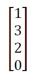
For example, if we have four inputs 1,3,2,0
Input set matrix is A
The one hot matrix B according to the algorithm is
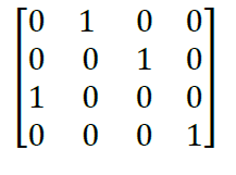
Transpose of hot matrix
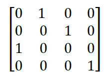
If one hot matrix is multiplied with the input matrix then the result is the sorted matrix in ascending in order

The transpose of this matrix is descending.
When this algorithm is implemented in hardware it does not need comparators but uses matrix mapping operations to achieve sorted output. For further details on this, the original paper can be studied.
Solution 2: Hardware sorting engine
This sorting hardware has been developed by Surajeet Ghosh, et al.[25]. Hardware sorting engine is a hardwarebased comparison free sorting that sorts N data items completely in N iterations. It finds the Largest Element (LE) in the 1st iteration. Thereafter, in every iteration, it finds the next LE from the remaining data elements. It uses two memory units unsorted memory unit and sorted memory unit. The input array is stored in unsorted memory. The hardware sorting engine receives data from unsorted memory and in every clock cycle, it detects the largest element and thereafter, it is been stored in a Sorted Memory (SM) unit. The overall controlling is done by the sorting controller.
The sorting engine consists of several cascaded blocks selected one after another. Given a set of N, n-bit wide data elements (with following bit representation of each element Dn-1, Dn-2….D0 with Dn-1 as MBS and D0 as LSB ) requires n blocks (block 1, block 2,….., block n). Each block is filtering the smaller elements and forwards the larger elements to the next block for further filtering and finally finding the LE among the participating elements. The largest element is added to sorted memory.
Each of these blocks consists of N number of basic cells that operate in a parallel manner. Each cell consists of a 2- input AND gate and a tiny switch (2×1 multiplexer). Since the cells present in a block run concurrently, The outputs of all 2-input AND gates of all the cells of the block (cells present in a certain block) are passed through an N- input OR Gate and the output of the OR Gate is used as a selection input to all the multiplexers present in each cell in that block. These multiplexers also receive two inputs, one from the respective cell’s 2-input AND gate (input 0) and another from the 2-input AND gate of the previous blocks corresponding cell (Input 1) (excepting the first block that receives input 1 from the element vector table EVT. EVT is an N bit register [B1, B2…BN] which are set to 0 or 1 depending upon whether the element from the unsorted memory has been added to the sorted memory or not, if it is added to sorted memory then the corresponding EVT entry is set to 0 or otherwise it is 1. At the beginning of every iteration, the Element Vector Table (EVT) reflects the data elements yet to be sorted. For the first iteration all the registers of EVT are equal to 1. At the end of each iteration, depending upon the result of the N-Input OR Gate either the input 0 or input 1 of the multiplexer is selected. If the output of the N-input OR gate is 1 then input 0 is routed into the output of the Multiplexers else input 1 is routed. The inputs to the 2-input AND gate of Block i (with i ranging from 1 to n) are bit Dn-i of each data element and the output of the multiplexer of Block i-1 however for the first block the two inputs to the 2-input AND gates are MSB i.e. Dn-1 of all the unsorted data items and EVT. For any other block i after the first block the two inputs to the 2-input AND gates are bit Dn-i of all the unsorted data items and the output of the multiplexers of the Block i-1.
Continuing this way, in the final block i.e. block n, the output of only one of the switches is always found high (for unique data entries). This indicates the bit position of the largest data element and with the help of the Largest Element Detector (LED) unit, LE (in certain iteration) is identified. However, for the duplicate entries, the output of multiple switches might turn high. This is resolved by imposing a masking logic before an ordinary encoder circuit. This masking logic along with the encoder unit is termed LED.
No of iterations is N.
Number, 3 bit in length n=3 and bit representation (D2,D1,D0) 4=(100), 0=(000) 1=(001) and 3=(011) ,no of bits in EVT register is therefore 4 EVT=[B1,B2,B3,B4] because there are 4 no’s with initial value of all bits set to 1 because no element has been added to sorted memory i.e. EVT[1,1,1,1] i.e. all its bits are set ( B1 corresponds to 4 ,B2 corresponds to 0, B3 one corresponds to 1 and B4 corresponds to 3) initially sort memory is empty . Number of blocks n=3 i.e. block1, block2, block3 In the first block following operation takes places.
Number of iterations=N=4
Bit representation of inputs
| Unsorted inputs | D2 | D1 | D0 |
|---|---|---|---|
| 4 | 1 | 0 | 0 |
| 0 | 0 | 0 | 0 |
| 1 | 0 | 0 | 1 |
| 3 | 0 | 1 | 1 |
Iteration No 1
Block 1
| Numbers in sorted memory | EVT | D2 (col 3) | EVT and D2 (col 4) |
|---|---|---|---|
| 4 | 1 | 1 | 1 |
| 0 | 1 | 0 | 0 |
| 1 | 1 | 0 | 0 |
| 3 | 1 | 0 | 0 |
OR all outputs of col 4 1+0+0+0+0=1 Outputs of AND (col4) transferred to block 2.
Block 2
| Previous and results (col1) | D1 (col 2) | Col1 and D1 (col 3) |
|---|---|---|
| 1 | 0 | 0 |
| 0 | 0 | 0 |
| 0 | 0 | 0 |
| 0 | 1 | 0 |
OR all outputs of col 3 0+0+0+0+0=0/Col 1 transferred to Block3.
Block 3
| Previous and results (col1) | D0 (col2) | D0 and D1(col 3) |
|---|---|---|
| 1 | 0 | 0 |
| 0 | 0 | 0 |
| 0 | 1 | 0 |
| 0 | 1 | 0 |
OR all outputs of col 4 0+0+0+0+0=0/Col 1 transferred to Block3.
| Previous col1 Col1 | D0 col2 | D0 and (col 1) (col3) |
|---|---|---|
| 0 | 0 | 0 |
| 1 | 0 | 0 |
| 1 | 1 | 1 |
| 0 | 1 | 0 |
Final output:
| Numbers in unsorted memory | Final output | New EVT for iteration 2 | Sorted memory |
|---|---|---|---|
| 4 | 1 | 0 | 4 |
| 0 | 0 | 1 | |
| 1 | 0 | 1 | |
| 3 | 0 | 1 |
Iteration no 2
Block 1:
| Numbers in unsorted memory | EVT Col2 | D2 col3 | EVT and D2 (col 4) |
|---|---|---|---|
| 4 | 0 | 1 | 0 |
| 0 | 1 | 0 | 0 |
| 1 | 1 | 0 | 0 |
| 3 | 1 | 0 | 0 |
OR all outputs of col 4 0+0+0+0+0=0 Outputs of col2 transferred to block 2
Block 2:
OR all outputs of col 3 0+0+0+0+1=1/Col3 transferred to Block3
| Previous EVT (col1) | D1 (col 2) | Col1 and D1 (col 3) |
|---|---|---|
| 0 | 0 | 0 |
| 1 | 0 | 0 |
| 1 | 0 | 0 |
| 1 | 1 | 1 |
Block 3:
OR all outputs of col 4 0+0+0+0+1=1 Col 3 transferred to final
| Previous EVT Col1 | D0 (col2) | D0 and D1 (col 3) |
|---|---|---|
| 0 | 0 | 0 |
| 0 | 0 | 0 |
| 0 | 1 | 0 |
| 1 | 1 | 1 |
Final output:
| Numbers in unsorted memory | Final output | New EVT for iteration 2 | Sorted memory |
|---|---|---|---|
| 4 | 0 | 0 | 4 |
| 0 | 0 | 1 | 3 |
| 1 | 0 | 1 | |
| 3 | 1 (LE) | 0 |
Iteration no 3
Block 1:
| Numbers in unsorted memory | Evt (col2) | D2 (col 3) | EVT and D2 (col 4) |
|---|---|---|---|
| 4 | 0 | 1 | 0 |
| 0 | 1 | 0 | 0 |
| 1 | 1 | 0 | 0 |
| 3 | 0 | 0 | 0 |
OR all outputs of col 4 0+0+0+0+0=1 Outputs of col2 transferred to block 2.
Block 2;
|
Previous col1 |
D1 col 2 |
Col1 and D1(col 3) |
|
0 |
0 |
0 |
|
1 |
0 |
0 |
|
1 |
0 |
0 |
|
0 |
1 |
0 |
OR all outputs of col 3 0+0+0+0+0=0 Col1 transferred to Block3.
Block 3:
| Previous col1 Col1 | D0 col2 | D0 and (col 1) (col3) |
|---|---|---|
| 0 | 0 | 0 |
| 1 | 0 | 0 |
| 1 | 1 | 1 |
| 0 | 1 | 0 |
OR all outputs of col3 0+0+0+0+1=1Col 3 transferred to final.
Final output:
| Numbers in unsorted memory | Final output | New EVT for iteration 2 | Sorted memory |
|---|---|---|---|
| 4 | 0 | 0 | 4 |
| 0 | 0 | 1 | 3 |
| 1 | 1(LE) | 0 | 1 |
| 3 | 0 | 0 |
Since only one element remains then in the next iteration it is also added to sorted memory.
| Numbers in unsorted memory | New EVT for iteration 2 | Sorted memory |
|---|---|---|
| 4 | 0 | 4 |
| 0 | 1 | 3 |
| 1 | 0 | 1 |
| 3 | 0 | 0 |
The hardware solution 2 is a comparison free sorting mechanism that does not require any sort of comparators, any complex circuitry or any complex algorithm (e.g., matrix manipulation as in solution 1) and involves only a few basic logic gates.it sorts N data elements in a linear sorting delay of O (N) clock cycles with an ability to find the largest data element in just a single cycle (1st cycle). For more details refer to the original work [25].
Special machine-level instructions for sorting
In addition to the development of hardware’s for sorting specialised instructions have been can be introduced in the instruction set of processors to implement sorting i.e. the software solution of sorting. Since these instructions are strictly dependent on processor architecture so this solution is a co-design solution i.e. both hardware and software solutions as one unit [26].
Many processors provide a set of Single Instruction Multiple Data (SIMD) instructions, such as the SSE instruction set or the VMX instruction set. These instructions can operate on multiple data values in parallel to accelerate computationally intensive programs for a broad range of applications. An obvious advantage of the SIMD instructions is the degree of data parallelism available in one instruction. In addition, they allow programmers to reduce the number of conditional branches in their programs [26-30].
Specialised Sorting algorithms can suitably exploit both the SIMD instructions and thread-level parallelism available on today's multi-core processors.
Sorting has an important role in DBMS systems. Two hardware instructions to assist sorting have been sorting in DB2 on IBM’s z-Series processors [31].
The conclusions of this study reveal that there is a great scope for developing better application-specific hardware for sorting that can accelerate and use a comparator free sorting. There is still a need to revisit this problem and look at non-conventional approaches to arrive at efficient results in terms of speed and memory. Designing a better algorithm is not the only way to make the sorting process efficient e.g. Like moving from O (n2) to more preferable O (n log n) solutions in comparison based algorithms. The process can be even bettered by using new hardware circuit designs.
Thanks to Prof Firdous Ahmad Mala (Head of Department) of Mathematics, Government degree College Sopore, for providing necessary guidance for the research work and helping me to write this paper. I would also like to thank Prof Joy Paulose (head of the department) of Computer Application, Christ University, Bangalore who has taught me and has been a source of inspiration.