ISSN ONLINE(2319-8753)PRINT(2347-6710)
ISSN ONLINE(2319-8753)PRINT(2347-6710)
Brindha.P1, Kaliamoorthy.M2, Arul prasanna.M3, Rajasekaran.V4
|
| Related article at Pubmed, Scholar Google |
Visit for more related articles at International Journal of Innovative Research in Science, Engineering and Technology
This work presents a novel single phase cascaded H-bridge multilevel inverter with least number of switches and isolated DC sources. The proposed inverter consists of two H-bridges connected in cascade. The upper H-bridge consists of five power electronic switches, capable of developing five level output and the lower H-bridge is capable of developing multilevel output. The conventional CHB inverter is replaced with the additional bi-directional switches in each cell. The proposed inverter consists of two H-bridges, the upper Hbridge is replaced with the addition of one bi-directional switch and the lower H-bridge is replaced with the bidirectional switches driven by hybrid modulation switching strategy. The upper inverter is switched at high frequency and the lower inverter is switched at low frequency. Hybrid modulation switching strategy is used to generate the multilevel output for the proposed inverter. The proposed inverter will be compared with the existing multilevel topologies on the basis of number of components, number of isolated DC sources, Switching losses and converter losses. The proposed inverter will be connected to the grid by proper synchronization along with maximum power point tracking algorithm. The proposed grid connected multilevel inverter will be simulated using MATLAB/SIMULINK and will be implemented in hardware using SPATRAN3A DSP.
Keywords |
| Cascaded inverters, Hybrid modulation, maximum power point tracking, Bi-directional switch. |
INTRODUCTION |
| Numerous industrial applications have begun to require higher power apparatus in recent years. For a medium voltage grid, it is troublesome to connect only one power Semiconductor switch directly. As a result, a multilevel power converter structure has been introduced as an alternative in high power and medium voltage situations. A multilevel converter not only achieves high power ratings, but also enables the use of renewable energy sources. Renewable energy sources such as photovoltaic, wind, and fuel cells can be easily interfaced to a multilevel converter system for high power applications [1]. |
| Over the past few years, technological advances in power electronics and increasing demand for energy have contributed to rapid development of power generation based on renewable energy sources. Photovoltaic (PV), Wind and Fuel cell (FC) based renewable energy technologies have attracted the attention of researchers over the globe. One of the problems focused in the research is the constraint of power electronic switches. If the power electronic devices which can prolong high voltage are used in the inverter, their switching frequency is restricted. Hence, the device voltage must be reduced to use high-speed switching devices. A multilevel inverter can reduce the device voltage and the output harmonics by increasing the number of output voltage levels [15]. |
| Further, increase in number of isolated DC sources in order to increase the number of output voltage levels leads to additional system complexity especially in PV and FC fed inverter topologies. The addition of isolated DC sources lead to the necessity of additional DC-DC converter, which are required to adjust the variable or low quality output voltage of the PV panels or FC stacks. Moreover power output of PV and FC stacks has to be maximized as it depends on the environmental condition. So in order to track the maximum power point of photo voltaic string or fuel cell stacks additional voltage and current sensors are required for each DC-DC converter. These additional sensors further increase the system complexity [6,7,8]. |
| In single-phase multi-level inverters, the most widely used techniques are cascaded H-bridge (CHB), diode-clamped and capacitor-clamped types [8-11]. In addition, many other techniques also exist [12-20]. In particular, among these techniques, CHB single phase inverters have drawn attention because of their modularized circuit layout and simplicity [9]. Abundant modulation techniques and control paradigms have been developed for multilevel converters such as sinusoidal pulse width modulation (SPWM), selective harmonic elimination (SHE-PWM), space vector modulation (SVM), and others. In this thesis sinusoidal pulse width modulation (SPWM) is used [15].By increasing the number of cascaded H-bridges, the number of levels in CHB inverters increases. Generally if the number of output voltage levels is increased, then the number of power electronic devices and the number of isolated DC sources is also increased. This makes a CHB inverter further complex. |
| In this paper, a novel multilevel inverter with minimum number of power electronic switching devices is proposed which is a modified version of the multilevel inverter using series/parallel conversion of DC sources (MLISPC) developed in [17]. In the proposed multilevel inverter, an auxiliary circuit comprising of four diodes and a switch is introduced instead of series/parallel switches of the inverter found in MLISPC. However, only two isolated voltage sources is needed to output the same number of voltage levels compared to conventional CHB [1,4,5] inverters and MLISPC. In the proposed multilevel inverter, an auxiliary circuit comprising of four diodes and a switch is introduced instead of series/parallel switches of the inverter found in MLISPC. However, only two isolated voltage sources is needed to output the same number of voltage levels compared to conventional CHB inverters and MLISPC. |
| Section II describes the circuit topology of the proposed multilevel inverter, comparison of the proposed topology with other topologies are discussed. . In Section III describes the hybrid modulation switching strategy. In Section IV, converter losses are discussed. In Section V, and VI, validate the simulation results. |
CI RCUIT TOPOLOGY |
| A. Overall System Structure |
| Fig.1 shows the block diagram of overall system structure, in which the PV string is connected to the DC-DC Boost Converter which tracks the sun to produce maximum power output from the solar array. Since the main application of the proposed inverter is fed from Photovoltaic (PV) array or Fuel cell (FC) stacks, DC-DC boost converters are required to boost the low output voltage of the PV panels or FC stacks. Hence here two boost converters are used one for the upper H bridge inverter and another for the lower H bridge inverter. |
| Hence, the DC-DC Boost Converter acts a maximum power point tracker. DC-DC Boost converters are used for two purposes they are, |
| 1. For boosting low output voltage of PV array or FC stacks to desired value. |
| 2. Balancing of DC link capacitors. |
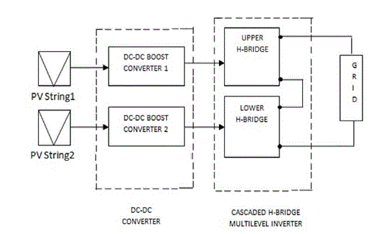 |
| Fig.1: Block Diagram of overall system |
| The DC-DC Boost Converter feds the power to the proposed novel single phase cascaded H-bridge multilevel inverter with least number of switches. The proposed inverter consists of two H-bridges connected in cascade. Here the solar array acts as a isolated DC source which drives the inverter circuit. The upper Hbridge consists of five power electronic switches, capable of developing five level output and the lower Hbridge is capable of developing multilevel output. The upper inverter is switched at high frequency and the lower inverter is switched at low frequency. The outputs from the inverter are fed to the grid by proper synchronization. The efficient design of inverter circuit allows feed the voltage depending upon the requirement of grid voltage. |
| B. Proposed Cascaded H Bridge Multilevel Inverter Structure |
| Fig.2 shows the circuit configuration of the proposed inverter with two H bridge inverters connected in cascade (Upper and lower H bridge inverters), where the inverter is driven by the hybrid modulation (HM) method. DC voltage sources Vdc0 - Vdcn may either be independent or dependent on each other. Here the magnitude of each voltage sources in the lower H bridge is two times the magnitude of upper H bridge voltage source ( i.e.,Vdcn = 2 Vdc0). The upper H-bridge is replaced with the one bi-directional switch and the lower H bridge of MLISPC is replaced with the bi-directional switches compared with the existing MLISPC. |
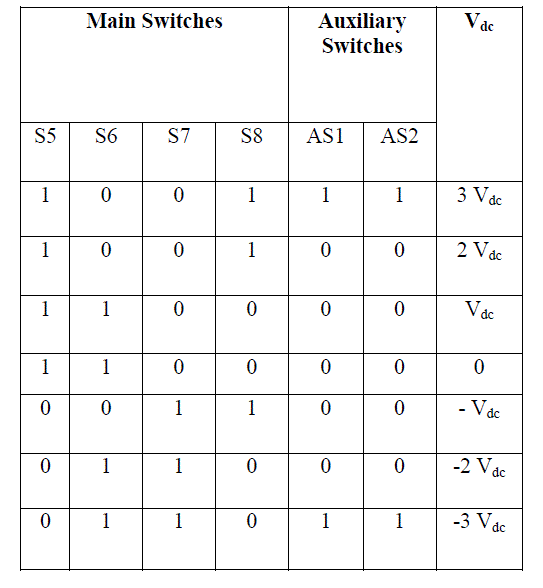 |
| Table I: Switching States of Lower H Bridge Inverter |
| As shown in Fig.2, in the upper H-bridge, an auxiliary circuit comprising of four diodes and a switch is placed between two DC sources and the lower H bridge, auxiliary circuit comprising of two bi-directional switches which is placed in between separates the DC sources. |
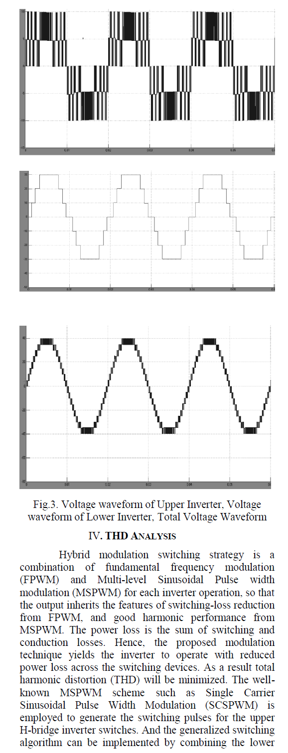
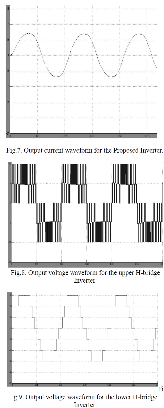
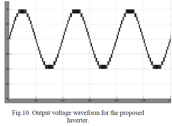
| Using this proposed circuit configuration, the upper H bridge inverter separately can outputs, Vup as five levels, while the lower H bridge inverter separately can outputs, Vlow as multilevel at its output because of increased number of bi-directional switches. Addition of one bi-directional switch increases the output level by four. In the proposed inverter structure the lower H-bridge inverter uses two bi-directional switches. The proposed inverter structure can outputs seventeen levels by combining the voltage levels Vup + Vlow or Vup - Vlow. |
| C. Comparison of Different Topologies of MLI |
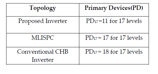
| When the traditional CHB inverter is driven by the Hybrid Modulation method 16 switching devices are needed for 15 levels with the ratio of Vdc0 : Vdc1 :Vdc2 :Vdc3 = 1:2:2:2. But in case of proposed inverter it requires only 11 switching devices with the ratio of Vdc0 : Vdc1 :Vdc2 :Vdc3 = 1:2:2:2.On the other hand, in order to produce 11 levels at the output whereas, MLISPC topology requires 11 switching devices and 2 DC sources In addition, to increase the level further by four, MLISPC requires an addition of three power electronic devices and one additional DC source. |
| In the case of proposed inverter, it requires only 9 devices and 2capacitor sources for 11 levels at the load voltage and 11 switching devices and 3 capacitor sources for 17 levels. Therefore ,when the output level increase, the difference between the required number of switching devices for the proposed inverter decreases drastically when compared with that of the conventional CHB inverters and MLISPC inverter. The proposed inverter can be smaller in size than the other two inverters because the number of switching devices is reduced significantly. Switching state of the lower H-bridge is shown in Table I. |
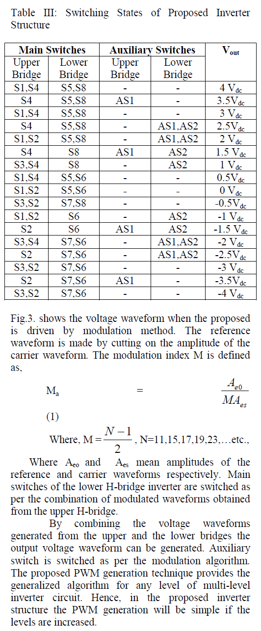
| Table II gives the component level comparison of different topologies of MLI.Table III gives the complete switching states and the derived output of the proposed multilevel inverter to generate 17levels. |
| Generally in the case of the asymmetrical cascaded H bridge inverters, it is possible to change the value of DC link or balancing capacitor voltage and sacrifice the redundancy in order to improve the quality of power by increasing the number of output voltage levels. Since in the proposed inverter, there exists only very little redundancy, balancing of capacitor voltages arises. Anyhow, the solution to the capacitor voltage balancing with reduced redundant levels is addressed in [15]. |
| Table II: Comparison of Different Topologies of MLI |
 |
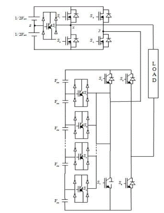 |
| Fig. 2: Proposed Cascaded H-Bridge Multilevel Inverter. |
HYBRID MODULATION SWITCHING TECHNIQUE |
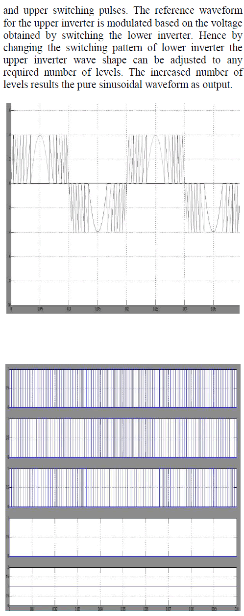
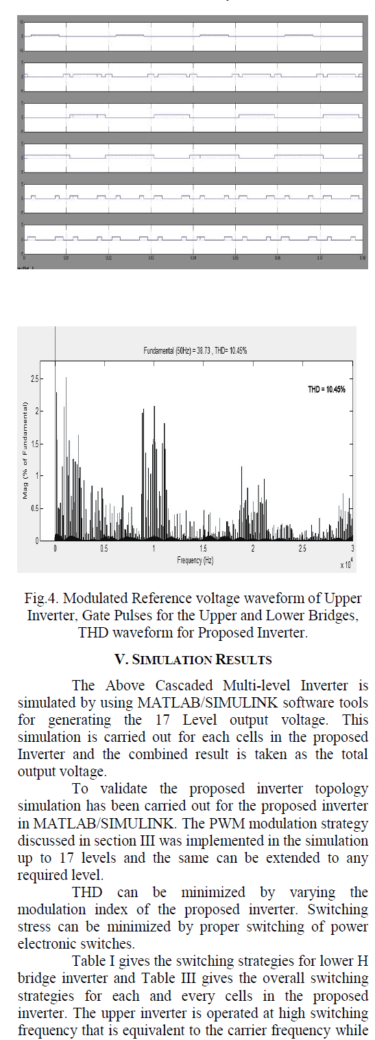
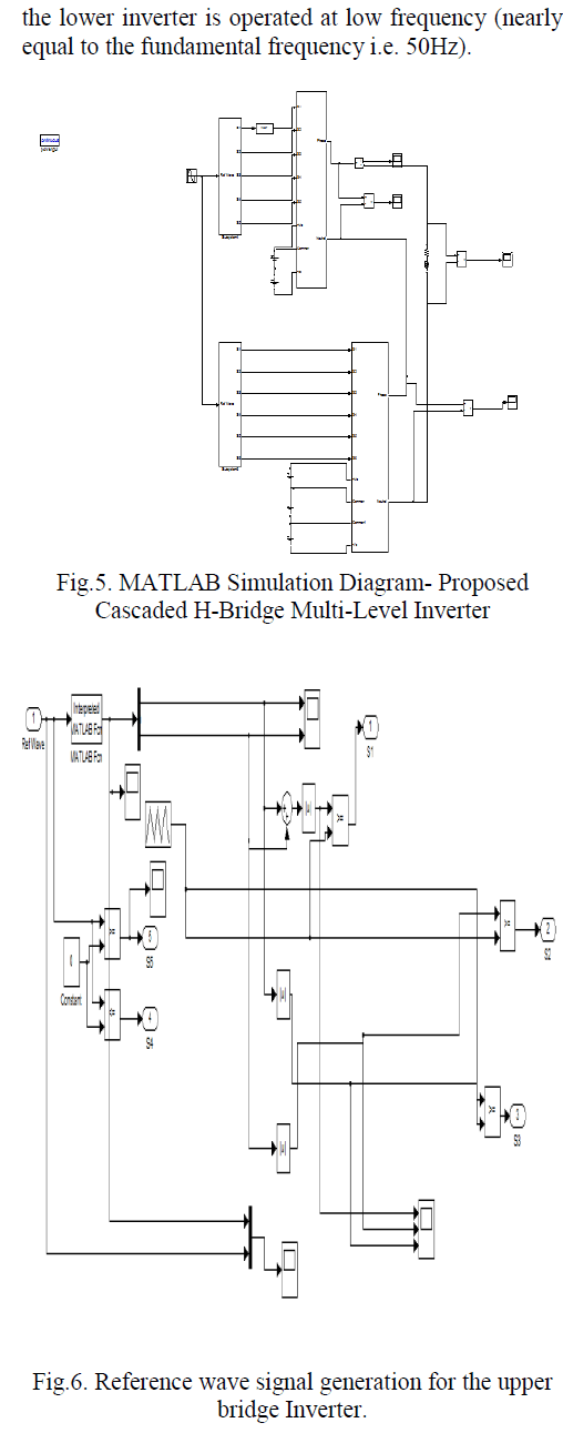
| This section describes the determination of switching function for getting output of seventeen levels in the proposed inverter. The same procedure can be extended to drive the switching function for N level inverter. A hybrid PWM modulation technique was used to generate the PWM switching signals. Hybrid modulation switching strategy is a combination of fundamental frequency modulation (FPWM) and Multilevel Sinusoidal Pulse width modulation (MSPWM) for each inverter operation, so that the output inherits the features of switching-loss reduction from FPWM, and good harmonic performance from MSPWM. The power loss is the sum of switching and conduction losses. Hence, the proposed modulation technique yields the inverter to operate with reduced power loss across the switching devices. The well-known MSPWM scheme such as Single Carrier Sinusoidal Pulse Width Modulation (SCSPWM) is employed to generate the switching pulses. Compared to conventional MSPWM schemes, less number of commutations and considerable switching-loss reduction is obtained by using this modulation scheme.In this modulation technique, the upper bridge switches are commutated at FPWM, while the lower H-bridge switches are modulated at MSPWM, therefore the resultant switching patterns are the same as those obtained with MSPWM. A sequential switching scheme is embedded with this hybrid modulation in order to overcome unequal switching losses, and therefore, differential heating among the power devices. |
 |
 |
 |
 |
 |
 |
 |
CONCLUSION |
| This paper has presents a novel single phase cascaded H-bridge Inverter with reduced number of power electronics devices and isolated DC sources. Simulations are carried out in MATLAB/Simulink. A Generalized switching algorithm which can be used for any number of levels is presented. The performance of the suggested novel cascaded H-Bridge multilevel inverter is investigated in detail. The modulation waveform and the harmonic analysis are also presented for various values of modulation strategies. By properly adjusting the modulation index, the required number of levels of the inverter output voltage can be achieved. This proposed inverter system offers the advantage of reduced switching devices and isolated DC sources when compared to the conventional CHB and MLISPC for the same number of output levels. Also, high frequency switching devices are operated at low voltage and low frequency devices are operated at high voltage. Thus it can be concluded that the proposed novel Cascaded H-Bridge Multilevel inverter can be used for medium and high power applications. The simulation results will be verified experimentally using SPATRAN3A DSP. |
References |
|