ISSN ONLINE(2319-8753)PRINT(2347-6710)
ISSN ONLINE(2319-8753)PRINT(2347-6710)
M.Dineshkumar1, R.Gandhi2
|
| Related article at Pubmed, Scholar Google |
Visit for more related articles at International Journal of Innovative Research in Science, Engineering and Technology
This paper presents a fast maximum power point tracking (MPPT) control algorithm for the photovoltaic (PV) in a hybrid wind–PV system, in which the PV generator may also need to work in a reduced power mode (RPM) to avoid dynamic overloading. The two control modes, MPPT and RPM, are inherently compatible and can be readily implemented, without the need of a dumping load for the RPM. Following the establishment of a dynamic system model, the study develops the guidelines to determine the variables of a direct hill-climbing method for MPPT: the perturbation time intervals and the magnitudes of the applied perturbations. These results are then used to optimally set up a variable-step size incremental conductance (VSIC) algorithm along with adaptive RPM control. The power tracking performance and power limiting capability are verified by simulation and experiment.
Keywords |
| Photovoltaic system, Wind system, Maximum Power Point Tracking, Rectifier, Inverter. |
INTRODUCTION |
| Saving Earth’s energy has become an important issue in this century because energy famine will occur after a few decades. The interest in solar power has been rapidly growing due to its advantages that include [6]: |
| i. Direct electric power form; |
| ii. Little maintenance; |
| iii. No noise; |
| iv. No pollution. |
| Since solar power uses the photovoltaic (PV) effect to transform solar energy into electrical energy, the PV panel is a nonlinear power source. The output power of a PV panel array depends on the PV voltage and unpredictable weather conditions [1]. In order to optimize the ratio between output power and installation cost, dc/dc converters are used to draw maximum power from the PV panel array Renewable energy, such as solar energy, is desirable for power generation due to their unlimited existence and environmental friendly nature. The many different techniques for maximum power point tracking of PV arrays are discussed. Maximum power point tracking (MPPT) is used in PV systems to maximize the photovoltaic array output power, irrespective of the temperature and irradiation conditions and of the load electrical characteristics [4]. |
| This paper is a continuation in building a hybrid wind–PV generation system. The main enhancement of the study is a solution regarding the overloading of the system which has happened in many occasions. The reduced power mode (RPM) of operation as proposed in this study can be used to suppress the oscillation due to the fast response of the PV generator. Furthermore, excessive solar radiation at a low temperature can also overload the power electronics in the system. Therefore, among all renewable energy sources, solar power systems attract more attention because they provide excellent opportunity to generate electricity while greenhouse emissions are reduced. It is also gratifying to lose reliance on conventional electricity generated by burning coal and natural gas. The PV generator should normally operate in the MPPT mode. Methods for MPPT include “open circuit voltage,” “short-circuit current,” “pilot cell,” and “hill climbing”. Because of the low cost and simplicity in using a dc/dc boost converter, “hill climbing” is perhaps the most widely used and is often implemented in a “perturb–observe” algorithm [2]. |
| However, the searching process for the maximum power point can easily fail to converge if the radiation changes rapidly and frequently. Incremental conductance (IC) is another interesting method which has previously been verified. To improve convergence, a variable-step incremental conductance method was proposed. A similar algorithm is proposed in this study with direct duty ratio adjustment [2]. |
WIND SYSTEM |
| Wind can be economically used for the generation of electrical energy. Heating and cooling of the atmosphere with generates convection current. Heating is caused by the absorption of solar energy on the earth surface and in the atmosphere. The rotation of the earth with respect to atmosphere and its motion around the sun. There are two primary physical principles by which energy can be extracted from the wind; these are through the creation of either lift or drag force (or through a combination of the two). The difference between drag and lift is illustrated by the difference between using a spinnaker sail, which fills like a parachute and pulls a sailing boat with the wind, and a Bermuda rig, the familiar triangular sail which deflects with wind and allows a sailing boat to travel across the wind or slightly into the wind. Drag forces provide the most obvious means of propulsion, these being the forces felt by a person (or object) exposed to the wind. Lift forces are the most efficient means of propulsion but being more subtle than drag forces are not so well understood [3]. |
| The basic features that characterize lift and drag are: |
| i. Drag is in the direction of air flow |
| ii. Lift is perpendicular to the direction of air flow |
 |
| Fig.1. Block diagram |
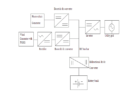
| Figuer1 shows a hybrid 2-kW wind–PV system with grid connection. In PV system the output dc is directly given to the boost dc\dc converter and is given to the dc bus bar. In Wind system the output ac is given to the rectifier and converted into dc and again given to boost dc\dc converter and is connected to the dc bus bar [3]. |
| The dc bus bar is also connected to the battery by using Bi-directional dc\dc converter and given to the battery .The wind speed is taken as a constant or variable speed conditions and for PV system we take a constant solar radiation input as 25 degrees. And both the voltage is connected to the battery bank by using a bi-directional dc-dc converter. We use MPPT algorithm in PV module to control the power in the system. So we can connect the two systems in the bus bar if voltage of system varies the converter changes it into a similar value of voltage in dc bus bar [4]. |
PV SYSTEM |
| There is an enormous supply of articles on the subject of photovoltaic power. Most articles are narrow in scope, perhaps announcing a recent breakthrough or discussing a particular project or application. The internet provides a great deal of information as well, with web sites sponsored by government agencies, industry groups, and manufacturers. We did have some difficulty finding an overview of the subject. Most books on photovoltaic are at least five years old and cover the technical aspect of photovoltaic without providing an assessment of the practicality of using photovoltaic's for power generation. The high cost of generating electrical power using photovoltaic cells compared to conventional coal-, gas-, and nuclearpowered generators has kept PV power generation from being in widespread use. Less than 1% of electricity is generated by photovoltaic. However, there are a few applications in which PV power is economical [7]. |
| These applications include satellites, developing countries that lack a power distribution infrastructure, and remote or rugged areas where running distribution lines are not practical. As the cost of photovoltaic systems drops, more applications become economically feasible. The non-polluting aspect of PV power can make it an attractive choice even when conventional generating systems are more economical. |
| The manufacture of photovoltaic systems has increased steadily for the last 25 years. It is Inevitable those engineers will be called upon to develop photovoltaic technology or will be involved in projects using this technology. Many existing reports on photovoltaic cover only one facet of the technology and sometimes writers inflate their reports on behalf of the company involved. There is a need for an up-todate, objective understanding of photovoltaic power generation. With this goal in mind we have created this report [12]. |
PHOTOVOLTAIC TECHNOLOGY |
| The simplest means of storage on a small or moderate scale is in electric storage battery especially a solar cell produces the direct electric current required for battery charging. A solar cell converts energy in the photons of sun light into electric city. A single solar cell can only produce a small amount of power. To increase the output power of a system, solar cells are generally connected in series or parallel to form PV modules [2]. |
| POWER RATINGS |
| Photovoltaic power generation systems are rated in peak kilowatts (kWp). This is the amount of electrical power that a new, clean system is expected to deliver when the sun is directly overhead on a clear day. We can safely assume that the actual output will never quite reach this value. System output will be compromised by the angle of the sun, atmospheric conditions, dust on the collectors, and deterioration of the components. When comparing photovoltaic systems to conventional power generation systems, one should bear in mind that the PV systems are only productive during the daytime. Therefore, a 100 kW photovoltaic system can produce only a fraction of the daily output of a conventional 100 kW generator. |
| THIN FILM TECHNOLOGY |
| Thin-film solar cells are manufactured by applying thin layers of semiconductor materials to a solid backing material. The composition of a typical thin-film cell is shown in Fig.2. Sunlight entering the intrinsic layer generates free electrons. The p-type and n-type layers create an electric field across the intrinsic layer. The electric field drives the free electrons into the ntype layer while positive charges collect in the ptype layer. The total thickness of the p-type, intrinsic, and n-type layers is about one micron. Although less efficient than single- and polycrystalline silicon, thinfilm solar cells offer greater promise for large-scale power generation because of ease of mass-production and lower materials cost [3]. |
| Thin-film is also suitable for buildingintegrated systems because the semiconductor films may be applied to building materials such as glass, roofing, and siding. Using thin films instead of silicon wafers greatly reduces the amount of semiconductor material required for each cell and therefore lowers the cost of producing photovoltaic cells. Gallium arsenide (GaAs), copper indium diselenide (CuInSe2), cadmium tellurides (CdTe) and titanium dioxide (TiO2) are materials that have been used for thin film PV cells. Titanium dioxide thin films have been recently developed and are interesting because the material is transparent and can be used for windows [2]. |
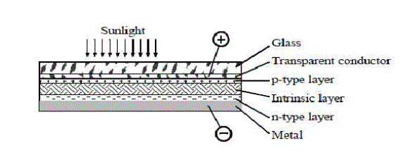 |
| Fig.2. Typical thin-film amorphous silicon construction |
| Tin Oxide Tin oxide is a conductive material that is transparent when in a thin layer. Tin oxide is used in place of a metallic grid for the top layer of thin film photovoltaic sheets. |
| Amorphous Silicon (a-Si) Amorphous (uncrystallized) silicon is the most popular thin-film technology. It is prone to degradation and produces cell efficiencies of 5-7%. Double- and triple-junction designs raise efficiency to 8-10%. The extra layers capture different wavelengths of light. The top cell captures blue light; the middle cell captures green light, and the bottom cell captures red light. Variations include amorphous silicon carbide (a-SiC), amorphous silicon germanium (a-SiGe), microcrystalline silicon (mc-Si), and amorphous silicon-nitride (a-SiN). |
| Cadmium Telluride (CdTe) and Cadmium Sulphide (CdS) Photovoltaic cells using these |
| Materials are under development by BP Solar and Solar Cells Inc. |
| Poly-crystalline Silicon Poly-crystalline silicon offers an efficiency improvement over amorphous silicon while still using only a small amount of material [10]. |
CONCENTRATING COLLECTORS |
| By using a lens or mirror to concentrate the sun’s rays on a small area, it is possible to reduce the amount of photovoltaic material required. A second advantage is that greater cell efficiency can be achieved at higher light concentrations. To accommodate the higher currents in the photocells, a larger metallic grid is used. For example, in a system with a 22X concentration ratio, the grid covers about 20% of the surface of the solar cell. To prevent this from blocking 20% of the sunlight, a prism is used to redirect sunlight onto the photovoltaic material, as shown in Fig.3. A second problem is the higher temperatures of a concentrating system. The cells may be cooled with a heat sink or the heat can be used to heat water. Only direct sunlight, not scattered by clouds or haze, can be concentrated. Therefore, the concentrating collectors are less effective in locations that are frequently cloudy or hazy, such as coastal areas [9]. |
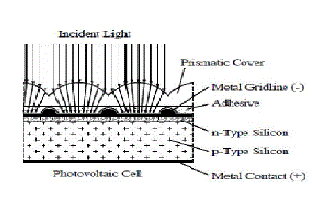 |
| Fig.3. Prism covers for high-current PV cell |
POWER CONVERTER |
| An ac to dc converter is an integral part of any power supply unit used in the all electronic equipments. Also, it is used as an interface between utility and most of the power electronic equipments. These electronic equipments form a major part of load on the utility. Generally, to convert line frequency ac to dc, a line frequency diode bridge rectifier is used. To reduce the ripple in the dc output voltage, a large filter capacitor is used at the rectifier output. But due to this large capacitor, the current drawn by this converter is peaky in nature. This input current is rich in low order harmonics. Also, as power electronics equipments are increasingly being used in power conversion, they inject low order harmonics into the utility [4]. |
| Converting AC (from mains or other AC source) to DC power by using power diodes or by controlling the firing angles of thyristors/controllable switches. |
| i. Input can be single or multi-phase (e.g. 3- phase). |
| ii. Output can be made fixed or variable. |
| THREE PHASE – SINGLE PHASE CONVERTER |
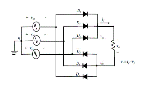 |
| Fig.4. Three Phase – Single Phase Converter |
| Top group: diode with its anode at the highest potential will conduct. The other two will be reversed. Bottom group: diode with it’s cathode at the lowest potential will conduct. The other two will be reversed [2], [11]. |
| BOOST DC-DC CONVERTER |
| The behavior of ideal inductive DC-DC converters in terms of the voltage conversion ratio k (δ) as a function of the duty-cycle δ and the conduction mode (CM) is discussed in this section. For this purpose the general small-ripple approximation method is provided here. The method is explained by means of an ideal boost DC-DC converter, which, but can be used for any given inductive DC-DC converter topology. As this method is only useful for calculations of ideal converters, it will prove to be of limited value in the design of monolithic inductive DC-DC converters. An accurate model for this purpose is provided [11]. |
| SINGLE PHASE INVERTER |
| The schematic of inverter system is connected, in which the battery or rectifier provides the dc supply to the inverter. The inverter is used to control the fundamental voltage magnitude and the frequency of the ac output voltage. AC loads may require constant or adjustable voltage at their input terminals, when such loads are fed by inverters, it is essential that the output voltage of the inverters is so controlled as to fulfill the requirement of the loads. For example if the inverter supplies power to a magnetic circuit, such as a induction motor, the voltage to frequency ratio at the inverter output terminals must be kept constant. This avoids saturation in the magnetic circuit of the device fed by the inverter [5]. |
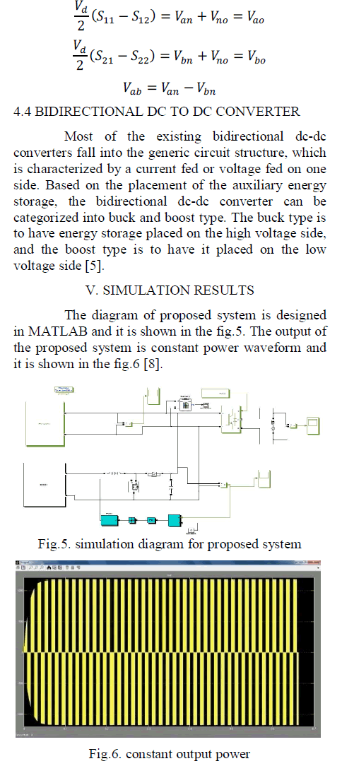 |
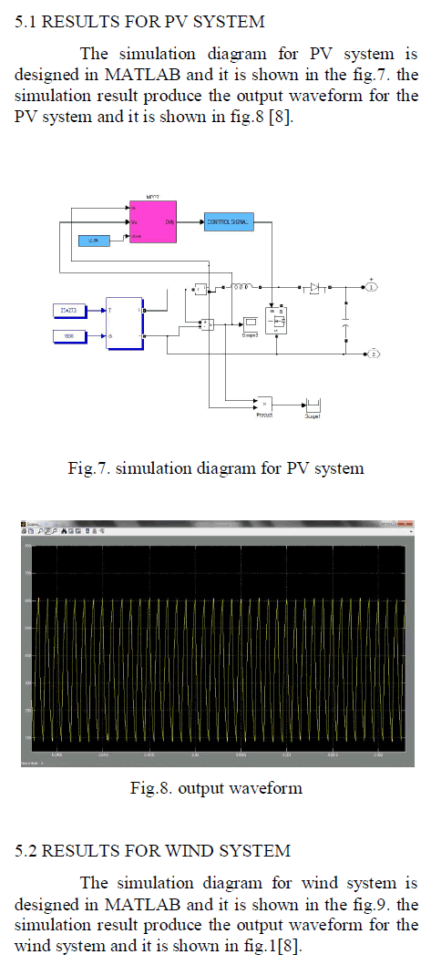 |
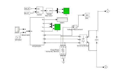 |
| Fig.9. simulation diagram for wind system |
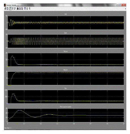 |
| Fig.10. output waveform |
CONCLUSION |
| The MPPT controller incorporating an RPM algorithm was developed in consistence with the previous design of the perturbation parameters. The proposed control algorithms based on a VSIC method. This is easy to implement in simple microcontrollers and is fast as compared to normal fixed-step IC and perturb and observe algorithms. The RPM was used to limit the output power of the PV generator if the generation exceeds the system rating due to reduced ambient temperature and high solar radiation. This mode can also be used when there is excessive energy to be stored in a stand-alone system. The proposed algorithm has been validated by simulation and laboratory experiment. It can be seen that the proposed algorithm can prevent oscillation and is able to quickly track the optimal operating point in severe transient conditions with changes of solar radiation and temperature [2]. |
References |
|