ISSN ONLINE(2319-8753)PRINT(2347-6710)
ISSN ONLINE(2319-8753)PRINT(2347-6710)
Dr.V.Anbumalar 1 , R.Mayandy 2 , K.Arun prasath 1, M.Raja Chandra Sekar 2
|
| Related article at Pubmed, Scholar Google |
Visit for more related articles at International Journal of Innovative Research in Science, Engineering and Technology
In today’s business world, competitiveness defines as an industry leader to drive towards maximum efficiency and it is constantly at the forefront of the companies objectives. Managers across the country are striving to adopt lean manufacturing practices to improve their bottom line cellular manufacturing and it helps to build a variety of products with as little scrap as possible. Layout a factory involves deciding where to put all the facilities, machines, equipment and staff in the manufacturing operation and layout determines the way in which materials and other inputs flow through the operation. Relatively small changes in the position of a machine in a factory can affect the flow of materials considerably. The facility layout in cellular manufacturing systems involve the arrangement of cells within the floor space, so as to minimize the inter-cell layout movement. The machine layout in cellular manufacturing systems involves the arrangement of machines within the cells so as to minimize the intra-cell movement and three basic types of machine layout is identified by as Single-row layout machines are arranged to the sequence of operations the layout may be assuming several types such as linear, Lshape, Multi-row machines are arranged in more than one row in this type of layout like U-shape, S-shape layouts and Loop layout here the machines are arranged around an oval path. In this paper we proposed to make a deliberate case study to study the existing layout design. We have designed the optimum layout considering different layouts like with an objective of minimize the cost by reducing the total travelling distance of materials processed in the industry through ARENA simulation software to produce better layout design for industry and its ability.
Keywords |
| Cellular Manufacturing, Layout design, Machine Layout, Manufacturing Operations, Factory Layout, ARENA simulation software, Process industry. |
INTRODUCTION |
| Cellular Manufacturing is a model for workplace design, and has become an integral part of lean manufacturing systems and it is based upon the principles of Group Technology, which seeks to take full advantage of the similarity between parts, through standardization and common processing. In Functional Manufacturing similar machines are placed close together (e.g. lathes, mills, drills etc.) with different shapes of arrangement of machines for production are identified Hassan.M.M.D [1]. Functional layouts are more robust to machine breakdowns, have common jigs and fixtures in the same area and supports high levels of demarcation. This allows workers to easily self-balance within the cell while reducing lead times, resulting in the ability for companies to manufacture high quality products at a low cost, on time, and in a flexible way[2]. This paper discusses the key areas that Characterize the identification in various implementations of cellular manufacturing methods to rectify the wastes. In the case study industry there is a situation of high degree of machine utilization along with the multitask labor and decrease in the overhead costs a high degree of contradictions has been observed in terms of quality to cost and training to overcome these issues, several factors were considered to improve the situation several tools of Lean Manufacturing concepts with various cellular manufacturing techniques were have been implemented. The important bottlenecks in the material handling system, equipment & space, WIP inventory, cost and other factors are have been studied and rectified. It is seen that the manufacturers face heightened challenges such as rising customers expectation, fluctuating demand, and competition in markets one way to stay competitive in this globalized market is to become more efficient. |
LITERATURE ASSESSMENT |
| D. Arun Kumar and V. Ramesh [3] has proposed in their case study in which a industry manufactures more than 45 different sizes of tubes for 9 different buyers and is one of the largest manufacturers of Automotive Butyl Inner Tubes in India. In the present plant layout the industries main plant has 8 major aisles the layout of straining section is optimized the change in position answers all the problems encountered in the straining section ,storage, precutting machine, material handling costs, floor space. Ronen Hadar and Arne Bilberg [4] had given the result of this development is a proof of concept of a changeable and reconfigurable assembly and decoration system based on the principles of RMS. Ineen Sultana and Imtiaz Ahmed [5], gave suggestions to manufacturing company which has to become competitive for its survival, it has to supply products of consistent high quality at reliable and reduced delivery time. Market also demands more product variants that means reduced lot size and high flexibility in operations and one successful solution has been the adopted. E.W.T. Ngai.et.al [6] has put forth a comprehensive review of research articles related to the application of decision support in the textile and apparel supply chains data were obtained from 77 articles published from 1994 to 2009 in 35 journals identified in this study provides insights and relevant references for both researchers and practitioners on the application of decision support and intelligent systems to various stages of a textile and apparel supply chain. Reza Salarian.et.al [7], proposed a mathematical model to formulate a cellular manufacturing system with uncertain parameters in this model, the processing time is a random variable following normal probability distribution, and demand is a random variable following normal probability distribution that the inter–cell movements are minimized and the bottleneck sore breakthrough. AydinAghajani.et.al[8],has developed dynamic mathematical model for designing of cellular manufacturing system in such a way dynamic cell configuration according to the presence of alternative process routings concept, system decides on the best routes for processing operations of parts instead of the user specifying pre–determined. Lisa Melandera and Fredrik Tell [9], said in their paper about their uncertainty which affects selection of suppliers and associated technologies, and selection outcomes in terms of commitment to one supplier or maintaining flexibility. Hyesung SeokShimon and Y. Nof, Recently [10], given an idea of demand and capacity sharing among independent and non-competitive manufacturers, at the same horizontal layer in SNs, has been studied through an appropriate coalition for collaborative demand and capacity sharing, manufacturers can minimize their lost sales, as well as maximize production capacity utilization against lumpy real demand. Dynamic collaboration results in more profits and its balanced redistribution by accommodating with changeable conditions. Riezebos [11] discussed about the facility layout used during lean implementation and can be either be a line layout or in the form of cells the rate at which work progresses through the factory is called flow rate or task based on task time for various parts, the production flow among cells was optimized thus minimizing several non-value added activities/times such as bottlenecking time, waiting time, material handling time, etc. Fatemeh Fardis.et.al [12], Clustering parts and machines into part families and machine cells is a major decision in the design of cellular manufacturing systems which is defined as cell formation. The objective function will minimize summation of idleness cost of machines, subcontracting cost for exceptional parts, non-utilizing machine cost, and holding cost of parts in the cells. Jayant H. Bhangale and Dr. Ashish M. Mahalle[13] has given the design of cellular manufacturing systems is complex for real-life problems. Two simplifying assumptions used in existing design methods are as follows routing flexibility of parts are not considered. Venkata Chalapathi Pasupuleti [14], has said that the more practical methodology has been proposed for detailed scheduling of all the jobs in the cellular manufacturing systems, considering the sequence of operation. Muamar M Musbah [15] has prescribed in his paper about the highlights and the benefits of using a simulation model for the cells and demonstrates the effects on the system during the fluctuation of projects, cells capacity, and clients schedule change the aim of the work was to develop a model that simulates a cellular manufacturing system to evaluate the systems behavior. Joseph C. Chen.et.al [16] is given a way to compete in this continuously changing environment, these organizations must seek out new methods allowing them to remain competitive and flexible simultaneously, enabling their companies to respond rapidly to new demands. Peetu Paul.et.al [17] says the industries are trying to adopt cellular layout for flexible production process with maintaining production rate. The objective of lean manufacturing is the aggressive minimization of waste, called muda, thereby improving efficiency of resources. Ripon Kumar Chakraborttya.et.al[18] has a view about the private Bangladeshi garment manufacturing companies are operating significantly below their potential capacity, or experiencing a high level of late-deliveries, due to problems with their current production scheduling and production management systems in this work. M. Murugan and V. Selladurai [19] share their views on the Percentage of Exceptional Elements (EE), Machine Utilization (MU), Grouping Efficiency (GE) and Grouping Efficacy (GC) are considered as performance measures the MCF methods considered in this comparative and evaluative study belong to the cluster formation approaches and have been coded by using C++ with an Intel P-IV compatible system. |
| David Kruger [20] told with the introduction of mass customization uniqueness and accessibility was addressed. South African manufacturers are facing growing international competition from low labor cost countries. Dr.R.Sampath and B.Senthil Kumar [21], suggested the same with new cellular based layout work in Progress (WIP) will be analyzed in all sewing room production line and the significance of WIP and its fluctuation is investigated through data obtained from sewing room production line and the reduction in WIP will increase the profit by 20-25 % from the existing level. Danny J. Johnson [22] made the framework is detailed enough to provide guidance to the industry practitioner on how to reduce manufacturing throughput time, while being general enough to apply to most manufacturing situations. Nikola SuziÃâÃâ¡.et.al [23] insists how to satisfy customer needs becomes increasingly complex when a product customization element is included the aim of the presented study is to show an application of production flow analysis in the process of converting the mass production company to a mass customization system. Kanagaraj.et.al [24], say about the reliability-based total cost of ownership approach which accounts both direct and indirect costs, as applied to the supplier selection process the mathematical formulation for supplier selection problem fits into the nonlinear integer programming problem, which belongs to the NP-hard category. Yu (Aimee) Zhang and Yong Yin [25], notifies the various similarity coefficients to the cell formation problem were investigated and reviewed. We also proposed a taxonomy which is combined by two distinct dimensions. For the further studies, we suggest comparative studies in consideration of some production factors, such as production volumes, operation sequences of parts and movement between the materials in office. |
PROBLEM IDENTIFICATION AND FORMULATION |
| A. Basic Details about the Production |
| The selected industry was located in Madurai this industry was started in 1998 and they are Wholesale Suppliers / Manufacturer / Exporters of sheet metal automobile components, oil seals, water pump seals, filter caps, elements, textile components, silent block components, break plates, industrial washers, brackets, clamps, pulley, sim plates, sheet metal components, metal products, press component for various Automobile industries around tamilnadu and other states in India. They are having 90 members and got very good infrastructure facilities such as Press shop having low to high Tonnage Power Presses & Hydraulic Presses ( 10 Tons to 150 Tons ) list enclosed Tool Room(M/s Tekhron India- Our sister concern) having 0.001 accurate Machineries. Spark erosion, cylindrical and surface grinding machines, shaping and DRO vertical milling, lathes, power hacksaw, drilling & vertical turret their main customers are Fenner India Ltd Madurai and Chennai they also made staged components like flange formed products and these made for Deccan Industries and PSI industries Hosur. They got their raw materials from Thirupthi Steels Chennai and Sun steels ,Ibrahim@co Madurai the steel which was used as raw material is CRDD M.S(Cold Rolled Deep Drawing Mild Steel) and it is in the size of 0.6to3mm of thickness this industry has 14 Power press with 13 pneumatic and 1 works with electric power according to the diameter of die sets may vary examples like (15 to 25mm-834die,25.1 to 38mm-1049die..) and the sequence of operation that required to make a oil shell are Shearing, Pressing, Grinding, Facing ,Visual inspection, Packaging, Dispatched. This oil seal is one of the important components for join two materials at air or liquid passed area. It has many types, required based on vehicles. Example Bike, car engines, gear box, etc. Mainly it’s made Fenner India ltd, TVS Rubber Ltd ,Hi- Tech Arai …etc,oil seal made from oil shell and it is produce by using cold rolled deep drawing quality mild steel then shell outer & inner area to cover rubber materials as per our required dimensions and the cost of making single oil shell including profit is about 1.34Rs and it took two to complete a set of product completely to packaging. And the distance between each machine about 900- 1000mm there are four labors and one supervisor who look after this production the problem which we observed here is the arrangement of machines and its layout design its is shown as a model and some of the data’s given by the industry from that we executed using ARENA software the results and the software model is shown below the problem here Fig:1 is the machines are arranged in oval shape but the press machines are idle when another machines are in work for 1 piece they want only one machine other 13 machines were in rest this increase the production and idle time of the work we made some alternate idea to make it simple and with good economy also improve the productivity with better output results. |
| Fig. 1 Arena model of on machine arrangement |
 |
 |
| TABLE: I Manual Calculation for Default Layout |
SOLUTIONS AND FINDINGS |
| In the modified layout design we have assigned the machine in linear layout model and the machines are separated according to the shape of the die or diameter and thickness of different capacity of machines with the regular operations which are involves to make a oil shell here we shown the linear arrangement of machines with two pressing diameters they are shown below Eg: 1)15 to 25mm thickness – 834die, they required 50T (2-30mm thick work piece use) machine for Pressing with sequence of operations as Shearing, Grinding, Facing, Visual inspection, Packaging, Dispatched similarly this layout for all type of dies and other process. |
 |
| Fig. 2 Arena model of linear machine arrangement |
| TABLE: II Software Calculations for Linear Layout |
 |
| Here we reduce the travelling distance of material it is simple due to the arrangement of machines closely with their required work and the production rate also quietly increasing they produced 107 (parts/hr) but that will increased as 155 (parts/hr).The distance between each material is reduced while we implement this machine layout for the process of making the oil shell in this layout is quiet about (500-650mm) also this type of layout requires only one supervisor and two helpers this optimum design to make the product with required time and less defective rate for linear movements of products. Eg: 2)15 to 25mm thickness – 834die, they required 50T (2-30mm thick work piece use) machine for Pressing with sequence of operations as Shearing, Grinding, Facing, Visual inspection, Packaging, Dispatched similarly this layout for all type of dies and other process. The same example is used to analysis the cost and same process involved but in different layout conditions now we select the L shape layout design for further analysis of layout with machine arrangements in correct sequencing order. |
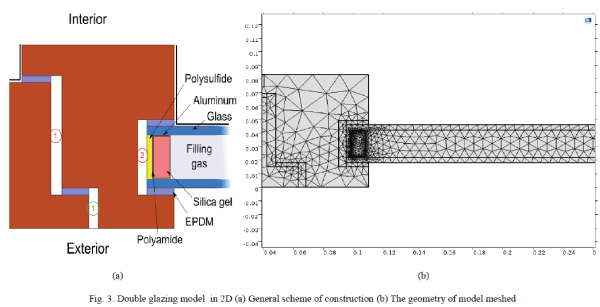 |
| Fig. 3 Arena model of L shape machine Layout |
| TABLE: III Software Calculations for L shape Layout |
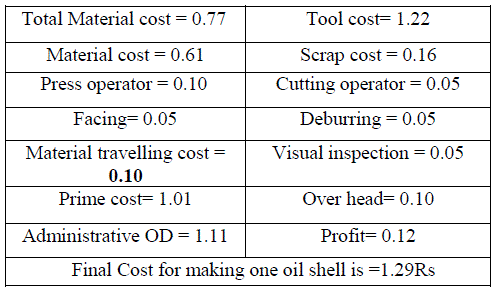 |
| In this L type machine arrangement design the travelling distance of material is reduced and the production rate is increased with 147(parts/hr) it is good layout design compare with their default design Fig: 1.The distance between each material is reduced while. We implement this machine layout for the process of making the oil shell in this layout is about (685mm) also this type of layout requires only one supervisor and with two helpers this optimum design to make the product with required time and standard shape with suitable size in large lot designs. |
| Eg: 3)15 to 25mm thickness – 834die, they required 50T (2-30mm thick work piece use) machine for Pressing with sequence of operations which was seen earlier in all type of layout while comparing this U shape layout may not provide optimum result. From the consequence which we got earlier but for the trial and error this will be executed and the results are shown here with the result of software simulation model, |
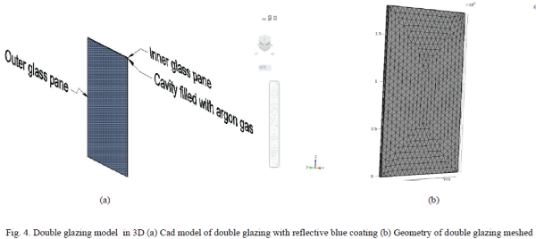 |
| Fig. 4 Arena model of U shape machine Layout |
| TABLE: IV Software Calculations for U shape Layout |
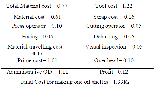 |
| This U type machine arrangement design the travelling distance of material is reduced and the production rate is 134(parts/hr) the distance between each material is reduced while we, implement this machine layout for the process of making the oil shell in this layout is about (685mm) in above design. But this machine arrangement requires more distance as more than (1000mm) deals with the placement of machine this expanse extra area. It is not suitable for this kind of industry in the machine layout. |
 |
| Fig. 5 Arena model of S shape machine Layout |
| TABLE: V Software Calculations for S shape Layout |
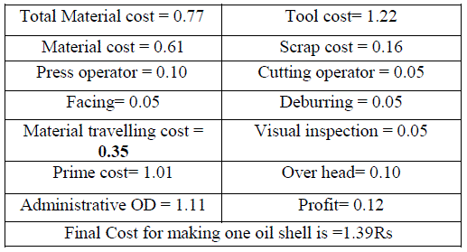 |
| The above value S type layout is not consider to be a suitable design for this type of process industry and moreover the machine arrangements also affect the sequence operation in the time of forming queue this will results in production. Here also we selected the earlier procedure with examples the outcomes are shown above with arrangement design but this will gives good result for process layout with their functional requirement of exports and import the product in more sustainable time. |
CONCLUSION AND FUTURE WORK |
| From the results we are getting from software and manually the analysis of various layout designs in both single-row and multi-row layout the main aim of this study is to identify the exact layout for proper Process industry. And moreover the major dilemma in this layout design is the idol time of machines, cost and the material movement between the each machine. They are clearly explained with the help of software ARENA and the executed results are compared using any of the quality tools here we used column chart to made the assessment between the layouts in fig: 6 the table no 2 mentions the optimum layout with the Rs of 1.26.Smilarly the 1, 3,4and 5 gives the result of other values as 1.39, 1.36, 1.29 from this the optimum layout is the linear layout for this selected process industry.This below column chart shows the different arrangement of machines in various layouts according to the simulation results. And the X-axis gives the details as different layout design also Y-axis is the total cost for making a single oil shell we gave the comparisons in the form of quality chart representation the machine design of layout No- 2 give the minimum cost with material movement and others are similar values with different layouts used in this paper. |
 |
| Fig. VI Column Chart Comparison between Layouts |
| And our future plan is to create different layout for a variety of process industry and provide best layout design with minimum of cost and travelling distance between the machines as well we planned to shrink the labor and layout problems regarding the machine arrangements in the various Process industry. |
References |
|