ISSN ONLINE(2319-8753)PRINT(2347-6710)
ISSN ONLINE(2319-8753)PRINT(2347-6710)
Sri Ganga Devi1, Mrs. A. Vasanthi2
|
| Related article at Pubmed, Scholar Google |
Visit for more related articles at International Journal of Innovative Research in Science, Engineering and Technology
Emerging Multicell Converters are very interesting alternatives for industrial applications. Here, an improved configuration of Double Flying Capacitor Multicell Converter (I-DFCM) is proposed. The major advantages of proposed converter is increasing the number of output levels with reduced number of switches and flying capacitors. The conventional configuration of DFCM converter is modified by additionally adding four low power switches and one minor dc voltage source. Added minor voltage source having a small fraction of voltage rating with main dc-link voltage rating to achieve 27-levels of output voltage. The proposed converter is controlled by a phase shifted carrier pulse width modulation technique. Simulation results are presented to validate the effectiveness of proposed I-DFCM converter. Furthermore, switching losses and total harmonic distortion are reduced. The functionality verification of the proposed 27 level I-DFCM converter with reduced number of switches is done using MATLAB/SIMULINK software.
Index terms |
| Improved Double Flying Capacitor Multicell Converter (I-DFCM), Phase Shifted Carrier Pulse Width Modulation (PSC-PWM). |
INTRODUCTION |
| Numerous industrial applications have been revolutionized in recent years due to the advent of Multicell converter. Some of the industrial application requires medium voltage and high power level. Multicell Converters has been introduced as an alternative in high power and medium voltage level. The major benefits of Multicell Converters in comparison with conventional system are synthesizing an output voltage with significantly improved Harmonic content, reduction of dv/dt and EMI. However, topologies of multicell converters are Flying Capacitor Multicell Converter (FCM), Stacked Multicell Converter (SMC), Double Flying Capacitor Multicell Converter (DFCM).FCM is made up of Flying Capacitor and a pair of switches with a complimentary state.SMC is stacking of two FCM converter together with upper and lower, upper stacks can be switched only positive voltage is required and the lower stacks can be switched only negative voltage required. Addition of low frequency switches to the conventional FCM converters are named as DFCM converter. DFCM with more additional switches and one minor dc voltage source comprises I-DFCM converter. It has many attractive properties for medium voltage application with transformer less operation and natural self balancing of capacitor voltages. Conventional FCM, SMC and DFCM converter uses bulky and costly flying capacitor. While, proposed IDFCM converter can reduced the number of switches and flying capacitors. The major advantage of proposed converter is number of voltage levels are doubled with reduced low power switches and one minor dc voltage source. |
| II-Improved Double Flying Capacitor Multicell Converter |
| The proposed I-DFCM converter has some advantages over DFCM, FCM and SMC converter. IDFCM converter increases the rms of the output voltage and number of output voltage levels. This can be achieved by adding switches to the configuration of a DFCM converter. While the number of switches and capacitors are reduced compared to other converter. The superiority of the I-DFCM converter over DFCM, FCM and SMC converter in producing the same voltage is the reduction of the number of switches and number of bulky and costly flying capacitors. Its cost and size of the converter reduces effectively. In order to achieve higher voltage levels these types of converters are more practical and cost effective. Fig 1 shows the circuit diagram of proposed I-DFCM converter. |
| In this paper, an improved configuration of I-DFCM converter is proposed to improve the increased voltage levels with reduced number of switches and capacitors; as a result it reduces the cost and size of the converter effectively. While other converters uses large number of capacitors for producing same voltage levels. |
 |
| Fig 1 circuit diagram of I-DFCM converter |
| III-Working Principle of I-DFCM Converter |
| The proposed I-DFCM converter uses one minor dc voltage source and a complimentary low power switches for producing increased voltage levels.The added minor voltage source and switches produces the minor voltage levels i.e odd levels. The DFCM converter produces major voltage levels i.e even levels. Therefore, the proposed I-DFCM converter as a sum of minor and major converters it can produces 27 levels in one unit steps. |
 |
| Fig 2 27 level proposed I-DFCM converter’s configuration, control strategy and switching states |
| The switching procedure of an 27 level I-DFCM converter is as follows. The absolute value of reference voltage Vref is obtained by intersecting Vref(reference signal) with 13 phase shifted carriers. |
| Comparison of Vref with 13 phase shifted carriers obtains Vref,abs absolute value of reference voltage. while Vref,abs is higher, when the comparator output is 1 and is lower, when the comparator output is 0.Then,the output of comparator are added together to generate staircase waveform of Vref,abs,s. Here, abs and s refers to absolute value and staircase waveform respectively. |
 |
| The reference of a DFCM converter Vref-DFCM is mainly calculated to produce the desired major voltage levels i.e even levels. Here a MATLAB embedded function is used to denote the even levels of output voltages. After calculating, the reference of DFCM converter is intersected with 6 phase shifted carrier, in order to determine the states of the converter switches i.e J,S1,S2....S6.Finally,Vref-DFCM is subtracted from Vref-mdf to calculate the status of switch K. Switch K is ON when it is 1,OFF when it is zero. While it is noted that K and K’ are complimentary switches. Table 1 shows the switching states of a 27 level I-DFCM converter. |
 |
| Table 1 switching states of proposed I-DFCM converter |
| It comprises 2n+2 high frequency switches with equal duty cycle and each having a phase shift of 2π/n and n- 1 flying capacitors. The comparison between the different types of multicell converter such as FCM, SMC, DFCM and I-DFCM converter for producing equal number of voltage levels are illustrated in Table 2. |
 |
| Table 2 Comparative analysis of various converter |
SIMULATION RESULTS |
| In this section, simulation results of proposed 27 level I-DFCM converter determines its good performance and Total Harmonic Distortion(THD).The simulation for the improved I-DFCM converter has done by using MATLAB/SIMULINK software. The output voltage of 27 levels has 13 levels in positive side and as well as in negative side. This can be achieved in I-DFCM converter. Totally 27 levels of output voltage from peak-peak levels. More number of levels can be obtained with reduced number of switches and flying capacitors compared with other converter. |
| The output of the I-DFCM converter is connected with resistive load. Conventional DFCM converter produces 11 levels of output voltage with large distortion. The distortion factor can be analysed using FFT analysis. Conventional DFCM has a THD of 18.73%.while proposed I-DFCM converter has a THD of 7.73%.The total harmonic distortion can be reduced in a proposed I-DFCM converter compared with conventional converter. |
| A.27 Level Proposed I-DFCM converter |
| The output voltage of the proposed six cell 27 level I-DFCM converter has a THD of 7.37%. This converter is operated with equal duty cycle and phase shift of 2π/n, controlled by the new modulation method (PSC-PWM) Phase Shifted Carrier Pulse Width Modulation. The frequency of PSC-PWM is 1kHz.The major converter produces major levels of output voltage 100V,200V,300V,400 V and the minor converter produces minor voltage levels i.e 33.3V between the major levels totally 27 levels of I-DFCM converter can be achieved by adding major and minor voltage levels. The frequency spectrum of output voltage has a harmonic around (k×13×1KHz) th harmonic where K is integer and 13 is voltage levels produced in half cycle. Table III shows the simulation parameters of proposed I-DFCM converter. |
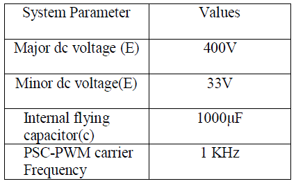 |
| Table 3 Simulation parameters of proposed I-DFCM converter |
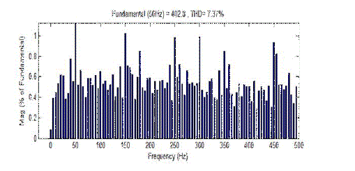 |
| Fig 4 THD output of proposed I-DFCM converter |
| V Comparison of I-DFCM With DFCM and FCM Converter |
| The size and cost of I-DFCM Converter is much lower than FCM converter in producing the same levels of output voltage. The main reason is that usage of number of switches, flying capacitors and dc voltage source of I-DFCM converter reduced compared with FCM converter. The price of I-DFCM converter is lower in comparison with DFCM converter. The major cost and size reduction components are switches, gate driver circuit and flying capacitor. The voltage rating of one dc-link in DFCM converter is equal to usage of two dc links in I-DFCM converter. Due to reduced number of switches in the I-DFCM converter, the required number of gate drivers is reduced in comparison with other converters. In general, the output of 27 levels I-DFCM converter needs (n-1) flying capacitor. While DFCM converter requires 2n flying capacitors. Moreover, reduction of size and components causes reduction of size in PCB. |
CONCLUSION |
| Flying capacitor based multicell converter such as FCM, SMC, DFCM and I-DFCM converters are mainly used for medium voltage and higher power applications. The proposed I-DFCM converter uses reduced number of cells and flying capacitors. This proposed converter is more practical and cost effective. These achievements are obtained by adding one minor voltage source with main dc link and low frequency switches to the conventional converter. The added cells and minor sources produce minor voltage levels between the major levels. Moreover, a new modulation method called PSC-PWM is implemented to control the new converter. Natural self balancing property still exists to balance the voltage rating of flying capacitor. This improved DFCM converter offers improved output waveforms and achieves lower THD. While compared to conventional system the voltage THD value is reduced from THD=18.85% to THD=7.37%.By this proposed I-DFCM topology the required number of switches and flying capacitors are reduced. The simulation results verify the good performance, THD and feasibility of the proposed converter. |
References |
|