ISSN ONLINE(2319-8753)PRINT(2347-6710)
ISSN ONLINE(2319-8753)PRINT(2347-6710)
B. J.Patil1, Dr. V. B.Sondur2
|
| Related article at Pubmed, Scholar Google |
Visit for more related articles at International Journal of Innovative Research in Science, Engineering and Technology
This research paper investigates the flow ripple of the hydraulic pumps. For the idealized case, an axial piston pump, gear pump and swash plate pumps with axial pistons are examined without leakage in to account. The number of pistons varied in case of axial piston pumps and the number of teeth on driving as well as driven gears are changed for the purpose of reducing the intensity of flow pulse. The effect of flow pulse on the pressure transition results of the pressure relief valve also investigated
Keywords |
| Flow ripple, Axial piston pump, Pressure relief valve, Pressure transition |
INTRODUCTION |
| Hydraulic pumps are the machines which are power supplying components in the hydraulic system. All pumps used in hydraulic systems are of the positive displacement type. No- positive displacement pumps usually supply low pressure and high flow rate. Positive displacement type pumps supply high pressure and low flow rate [1]. The detailed classification of the pump is shown in figure 1 |
 |
| Fig. 1Classification of hydraulic pumps [1] |
| The rotodynamic pumps increase the kinetic energy of the oil due to the momentum exchange between the oil and the rotor. The displacement pumps act to displace the oil by contracting their oil filled chamber. So the oil pressure increases and the oil is displaced out of the pumping chamber. The special effect pumps are jet pump and airlift pump. |
RELATED WORK |
| Boy-Ying Jaw and Honggchin Lin described the output of the PMOD charge pumps in connection with the importance of on-resistance of switching transistor. He developed the analytical model which is also verified by simulation tools like CMOS technology. The result was only within error of 7%[4]. Dong- Hee Lee, Tae-Hyoung Kim and Jin-Woo Alm worked for hydraulic pump of the naval direct instantaneous pressure controller system. To reduce the torque ripple, he developed the torque controller and obtained the smooth torque[5]. |
| Noah D Manring worked on the topic of axial piston swash plate type hydraulic pump. He explained the piston movement is in the form of harmonic motion, and which results in to the sinusoidal law. The product of piston area and speed gives the flow rate. The total flow rate is product of the number of piston and the flow rate by each piston. The discharge will be done by two or three pistons at a time [6]. |
CAUSES OF PULSES OF FLOW RATE |
| There are two reasons to induce pulses in flow of pump in hydraulic system. Viz. 1) pump ripple 2) ambient noise. |
1) Pump ripple is occurring in axial piston as well as in external gear pump. |
| 1.1 In case of axial piston pump the piston movement is in the form of harmonic motion, obeying the sinusoidal law. The flow rate by each piston is product of piston area and speed. The figure 2 shows the flow rate from each piston of a five piston pumps without considering the internal leakage, fluid inertia and compressibility of oil. The pump delivery is the summation of the flow rate delivered by all of the pistons in connection with the delivery port[1]. There are either two or three pistons discharging at the same time and the total pump flow rate is shown in figure.2 |
 |
| Fig. 2 flow rate and pressure pulsation of a five radial piston pump.[6] |
| The pressure and flow rates are plotted in non-dimensional form relative to the mean values Pm and Qm |
| Q1=Q/Qm, (1) |
| P1=P/Pm (2) |
| The flow pulsations are calculated for axial piston pumps for different number of pistons neglecting the compressibility of oil, internal leakage. The calculated results are plotted in figure 3 From the figure we can come to know that flow pulsation can be reduced by using greater odd number of pistons (Z=9). Because of the pulse nature of pump, the oscillations occurred in the results as shown in experimental results. |
 |
| Fig.3 Effects of the number of pistons on the flow rate and pressure pulsation [6] |
| 1.2 External gear pump: in case of external gear pump is shown in figure 4. The gear pump is used for displacing fluid. The number of teeth on gear 1 is denoted by N1 and the number of teeth on gear 2 is denoted by N2. The oil is carried around the outside of each gear from the intake side of pump to the discharge side of the pump. as the gear teeth mesh within the gear set. The oil is squeezed out of each tooth gap by a mating tooth which helps to displace the oil into the discharge line of the pump. the teeth will come out of the mating on the side of the intake. In this situation the oil backfills for the volume of the mating teeth which are now evacuating each tooth space. The backfilling draws oil into the pump through the intake port of the pump chamber. This process repeats itself for each rotation of the pump and hence displaces oil at a rate of proportional to the speed of the pump[2, 3]. |
 |
| Fig.4 Gear pump |
| The pump with the combination of tooth on the pinion as well as on the gear is taken for the study. The figure 5 shows the pump with different combination of gear teeth. |
 |
| Fig.5 Gear pumps of the same displacement for different numbers of teeth on the driving and driven gears. |
 |
| Fig.6 The theoretical flow rate pulse for the pumps[5] |
| The figure 6 shows the plot of the flow pulse for different combination of gear teeth. From the figure we can come to know that by increasing the number of teeth on the driving gear, the flow pulsation can be reduced. |
| 2) Noise in hydraulic system:- one of the major problem in the hydraulic system is the noise produced by the system. The noise produces the pulses of flow. The noise generation in axial piston pump can be classified into two category viz. 1) fluid-borne noise 2) structure borne noise.3) air borne |
 |
| Fig.7 Hydraulic system noise generation andtransmission |
| The figure shows the noise generation and transmission in hydraulic system. The kinematic ripple is the main cause of the fluid borne noise. The fluctuating forces and moments of the parts causes the generation of structure borne noise. Both FBN and SBN causes high fatigue loads on the system components and make them to vibrate. The vibrations are radiated as air borne noise. The air borne noise can be reduced by reducing the FBN and SBN and also by using suitable design modification of the parts so that it radiates least amount of noise. |
EFFECTS OF PULSE FLOW ON THE PRESSURE TRANSITION TEST |
| The pressure relief valve DPRS06K315 is modelled in Matlab/simulink. The model is simulated to determine the performance of the valve subjected to impact load at set pressure of 130 Bar is as shown in figure to represent theoretical result without considering the pulse flow of the pump. The time response of the valve to bring stable is 0.08 seconds. |
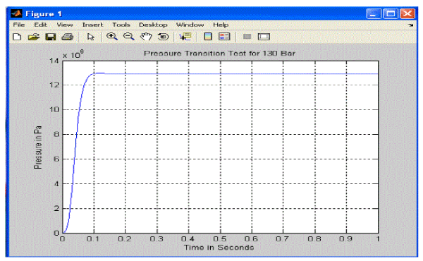 |
| Fig. 8 Simulation result for the set pressure 130 Bar |
| The same pressure relief valve DPRS06K315 is tested to determine the performance of the valve at set pressure of 130 Bar subjected to impact load experimentally. The time response of the valve to bring stable is 0.08 seconds. The oscillations are occurred during the result as shown in figure 9. The reason for the oscillations is the pulses of the flow rate. |
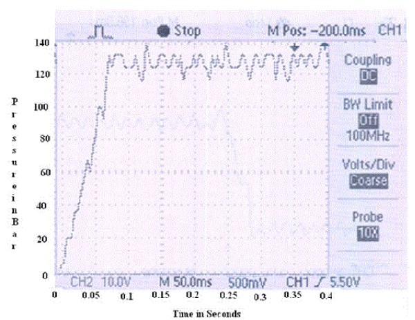 |
| Fig. 9 Experimental Pressure transition test for 130 bar |
CONCLUSION |
| The pulse of flow can be reduced by using greater odd number of pistons in case of axial piston pump. The pulse of flow can be reduced by using by increasing the number of teeth on the driving gear in case of external gear pump. The oscillations occur due to the pump flow rate pulses and the hydraulic system noise on the result. |
ACKNOWLEDGEMENT |
| I would like to take this opportunity to thanks Mr. Anand Samant, Managing Director, PSPL, Belagavi. and Late shri Suresh Hundre, Polyhydron Pvt. Ltd., Belagavi and Siddhartha Hundre, Corporate Manager, Polyhydron Pvt. Ltd, Belagavi, who allowed me to analyse the valve for research from their organisations. |
References |
|