ISSN ONLINE(2319-8753)PRINT(2347-6710)
ISSN ONLINE(2319-8753)PRINT(2347-6710)
A A Shaikh 1, A M Varsi 2
|
| Related article at Pubmed, Scholar Google |
Visit for more related articles at International Journal of Innovative Research in Science, Engineering and Technology
Emergence of advanced engineering materials, stringent design requirements, intricate shape and unusual size of workpiece restrict the use of conventional machining methods. Laser Beam Machining (LBM) is one of the advance manufacturing processes which are used for shaping almost whole range of engineering materials. The present work deals with the study of varying pressure and traverse speed by CO2 lasers for cutting the acrylic material and the attempt is made to develop a model to predict the depth of cut for 25 watt machine. The variation pattern for cutting depth is discussed about the convergence of predicted and experimental results.
Keywords |
| Advance machining, Laser cutting, Single pass, Melting. |
INTRODUCTION |
| In a recent era many advance manufacturing processes are being used in the industry such as; electro-discharge machining, beam machining processes such as Laser beam machining (LBM), electron beam machining, ion beam machining and plasma beam machining), electrochemical machining, chemical machining processes, ultrasonic machining (USM), and jet machining processes, but these processes have their own limitations regarding workpiece material, shapes, etc. LBM is one of the advance manufacturing processes (AMPs) which are used for shaping almost whole range of engineering materials. The laser beams are widely used for cutting, drilling, marking, welding, sintering and heat treatment. The laser is also used to perform turning as well as milling operations but major application of laser beam is mainly in cutting of metallic and non-metallic sheets [1]. When the laser beam gets focused on the workpiece, the material removal takes place by the method of melting and vaporization. The material removal takes place by the suction process of compressor attached with the laser machine. In order to achieve the required depth, the probe has to be moved number of times for a given set of parameters. Laser machining is accomplished when the work piece absorbs laser energy and this photon energy gets converted into thermal energy. The high peak intensity of the pulse generates strong evaporation pressure which is responsible for ejection of this molten material and material loss at the surface due to evaporation for generation of machined depth [2]. K. A. Fenoughty, et al [3] have claimed that there are various benefits that can be gained from using lasers as cutting tools, which include no tool wear, ease of automation, small heat-affected zones and virtually no restrictions on the geometries that can be cut. The important parameters involved with any laser process are the diameter and power of the beam and the velocity at which the beam traverses the material's surface (and hence the interaction time). I. A. Choudhury, et al [4] had investigated about CO2 laser cutting of three polymeric materials each with the aim of evaluating the effect of the main input laser cutting parameters (laser power, cutting speed and compressed air pressure) on laser cutting quality of the different polymers and developing model equations relating input process parameters with the output. J. Paulo Davim, et al [5] presents a preliminary study to evaluate the effect of the processing parameters (laser power and cutting velocity) under the quality of the cut for several polymeric materials. C. Y. Jiang, et al [6] established a theoretical model to predict the depth of machining by considering the laser beam intensity distribution and the interaction of the beam with the material. The experimental results show that the depth of cut increases with the increasing number of pulses at the beginning and then a saturation state is reached. H.A. Eltawahni, et al [7] presents a means for selecting the process parameters for laser cutting of MDF based on the design of experiments (DOE) approach, where CO2 laser was used to cut various thicknesses of MDF panels. The process factors investigated are: laser power, cutting speed, air pressure and focal point position. L.D. Scintilla, et al [8] studied the influence of processing parameters and laser source type on cutting edge quality of AZ31 magnesium alloy sheets and observe differences in cutting efficiency between fiber and CO2 lasers. It was also observed that fiber laser allows to obtain best quality of cutting edge and although dross height is lower for CO2 laser cut, the attached dross on the lower part of the cutting edge is discontinuous, slightly adherent and easily removable. An increase in cutting speed has the effect of reducing the extension of striations, roughness and dross height. B. Tirumala Rao, et al [9] presented work which aimed at studying the dynamic behavior of melt ejection in laser cutting of titanium sheet for obtaining dross-free cuts with minimum heat affected zone (HAZ). The results reveals use of He as the shear gas brought about significant reduction in dross formation. Shear gas not only serves to drag the melt out of the kerf but also causes cooling of the melt front. Cooling effect of the shear gas becomes relatively more dominant at higher gas pressures. This effect seems to be responsible for relatively lower rise in maximum cutting speed at higher gas pressure while using Ar as the shear gas. L. Romoli, et al [10] studied CO2 laser machining of a suitable amorphous polymer (PMMA) for the rapid fabrication of miniaturized structures such as micro fluidic devices. Results revealed that the depth of a layer is inversely proportional to the scanning step. The reason for this behavior can be attributed to thermal accumulation due to the much greater number of passes needed to machine the same rectangular layer using small values of the scanning step. As a result, the irradiation time increases and a large amount of heat cannot be eliminated by conduction due to the low thermal diffusivity of PMMA. The objective of the present work is to carry out laser machining by CO2 laser on acrylic sheet by varying cutting parameters like power and cutting speed for single pass of laser probe and development of predictive model for comparison purpose for the system used. |
EXPERIMENT |
| The experimental apparatus consisted of a CO2 laser (Mercury Laser pro machine) with a maximum continuous-wave output of 25 W, a beam delivery system with a 5 cm focal length lens producing a focused beam diameter of approximately 0.015 cm, and a workpiece positioning system with three degrees of freedom. An air jet was used with the laser beam to protect the lens and expel molten material from the machined zone. The cutting experiments were performed on acrylic sheet since its absorptivity is unity. The cutting parameters considered are laser power (p) from 0 to 100% of maximum capacity 25 watt, while and cutting speed (v) from 0 to 100% of maximum capacity of 42 ips (1066 mm/sec). The present experiment is planned for one pass of cutting to observe generation of depth of cut. Laser cutting modes are of two types: (i) Raster and (ii) Vector. A raster mode will make back-and-forth motion to create the shape whereas a vector mode will follow the path of the outline of the shape. The schematic diagram for the path of motion of laser beam in vector and raster mode is shown in Fig. 1. |
 |
| The machine used for experiment allows the use of 16 different colors to represent various power and speed settings for cutting and engraving. These colors are referred to as PENS responds to options of raster and vector mode. This facilitates cutting of various combination of selected parameters at a time. In order to perform cutting on laser machine, a pre processing software is used for creating 2D profile with fill option so as the material can be targeted by machine in that region to melt it and evaporate. The software also creates an interface to transfer geometry information between computer and the machine. The present work attempts creation of cavity of 10 mm diameter with fill option so as the machine can create circular cavity of 10 mm with certain value depth based on the set parameter combinations. The case of creation of such cavities by considering constant power, 100%, and various cutting speeds like 10%, 19%, 28%, 37%, 46%, 55%, 64%, 73%, 82%, 91% and 100% is highlighted in Fig. 2. The similar runs were taken for various powers setting so as to generate 121 sample cavities for study of depth of cut obtained. |
 |
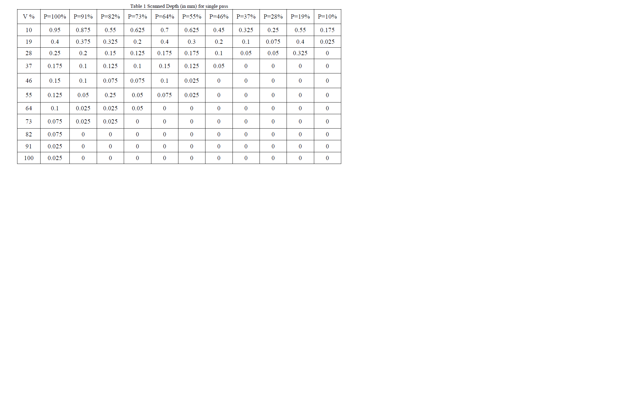
| The measurement of depth of cut for all cavities were carried out on Rolland make needle scanner to read each spot as point and gives collective information as point cloud data. The interfacing software continuously provides the detail of building of point cloud data which can be easily visualized on screen. Such visualization screen and photograph of acrylic plate with all cavities are depicted in Fig 3. The depth value in individual cavity is considered for average value of specific combinations is calculated, and the same process is repeated for all combinations considering 121 cavities. The data of depth values for varying pressure and traverse speed are depicted in Table 1. |
 |
| The reported value of depth of cut for each combination of cutting parameter is further used for developing predictive model. |
 |
DEVELOPMENT OF ANALYTICAL MODEL |
| During the process of cutting with CO2 laser, it was found that as power increases, depth of cut increases while as speed increases, depth of cut decreases. Thus, depth (d) is directly proportional to power (P) and inversely proportional to speed (V). |
| Mathematically, |
 |
| Therefore, removing the proportionality sign and placing constant b, |
 |
| In the above equation (3), d is a dependent variable while P and V are independent variable. Hence, by doing multivariable regression analysis, the constant b can be obtained. The multivariable linear equation is given by [11] |
 |
| Using the above methodology, the calculations pertaining to the set of data obtained for single pass depth of cut for various power and speed combinations is done and finally, the value of constant b is obtained. Hence, equation (3) can be rewrite as |
 |
| Where, b = 0.081523941 |
| The above equation (11) gives the value of depth of cut for a particular power and speed for a single pass. Calculating the depth from the above equation and doing the regression with the experimental depth value, the value of average error comes to be 4.5% which shows good convergence from the actual one. |
RESULTS AND DISCUSSION |
| The results obtained by cutting experiments are analyzed and discussed in this section. This is done in two parts: (i) Influence of power on depth of cut for different speeds and (ii) Influence of speed on depth of cut for different powers. |
| 4.1 Influence of power on depth of cut for different speeds |
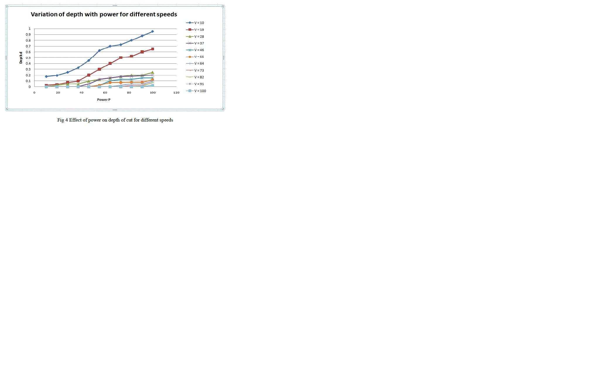 |
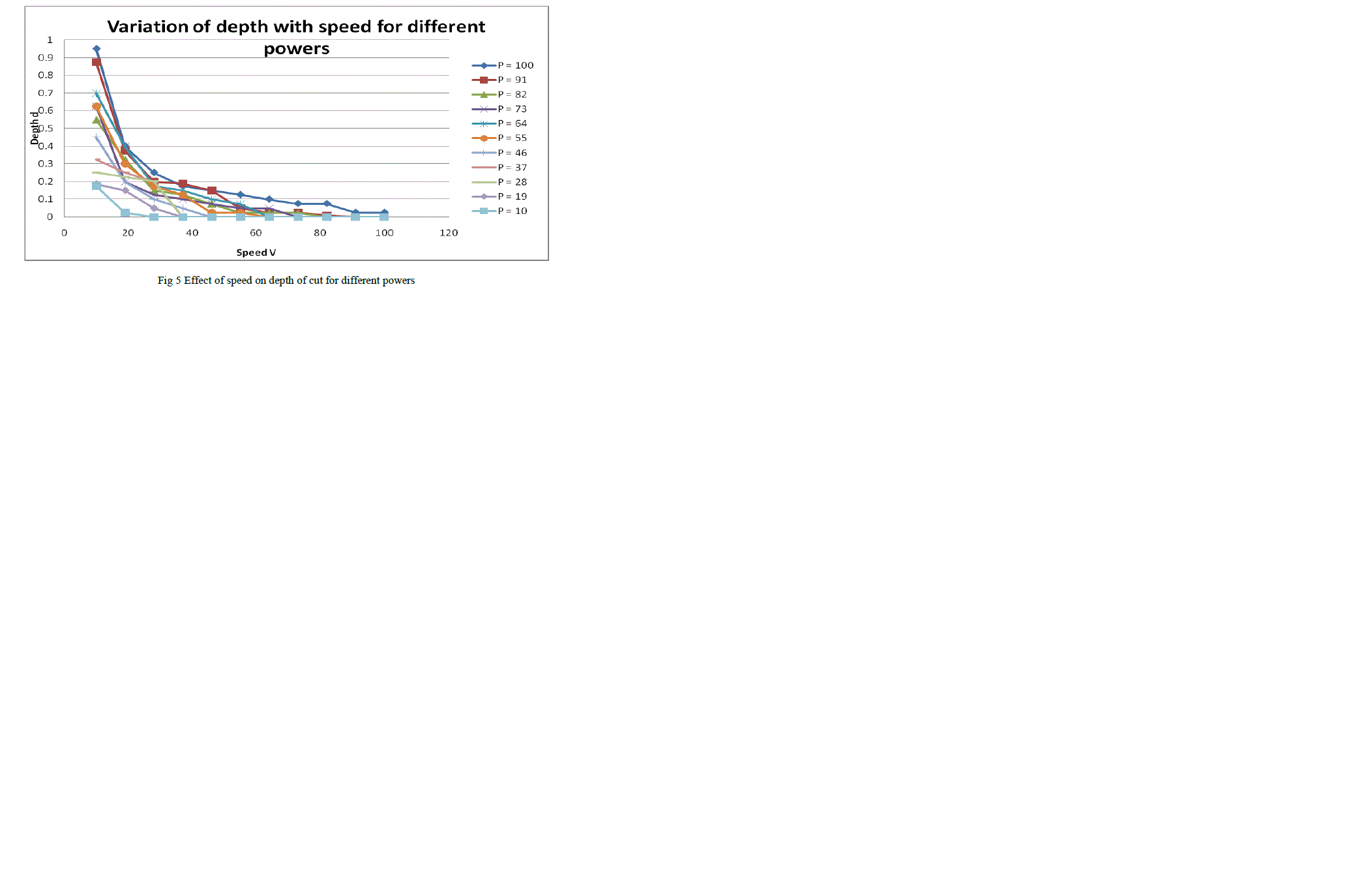
| The Fig 4 depicts that as power increases, depth of cut also increases for particular speed and the same trend is observed for all value of speed. However the value of speed increases, the quantifying trend of the graph goes down showing the decrease in the value of depth of cut due to reduction in contact time, which is responsible of transfering less amount of energy. The Fig. 5, highlights that as speed increases, depth of cut decreases for particular power and the same trend is observed for all values of powers. However the value of power increases, the trend of the graph goes up as amount of energy transfer also increases. |
| 4.2 Influence of speed on depth of cut for different powers |
 |
| 4.3 Assessment of Predictive Depth for Single Pass |
| The depth of cut is the function of power and speed. Hence the resultant equation for predicted depth for single pass is given by: |
 |
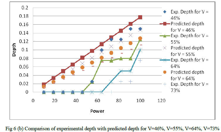
| Using the above formula, the comparison of experimental depth with predicted depth is shown in the graph below for constant speeds: |
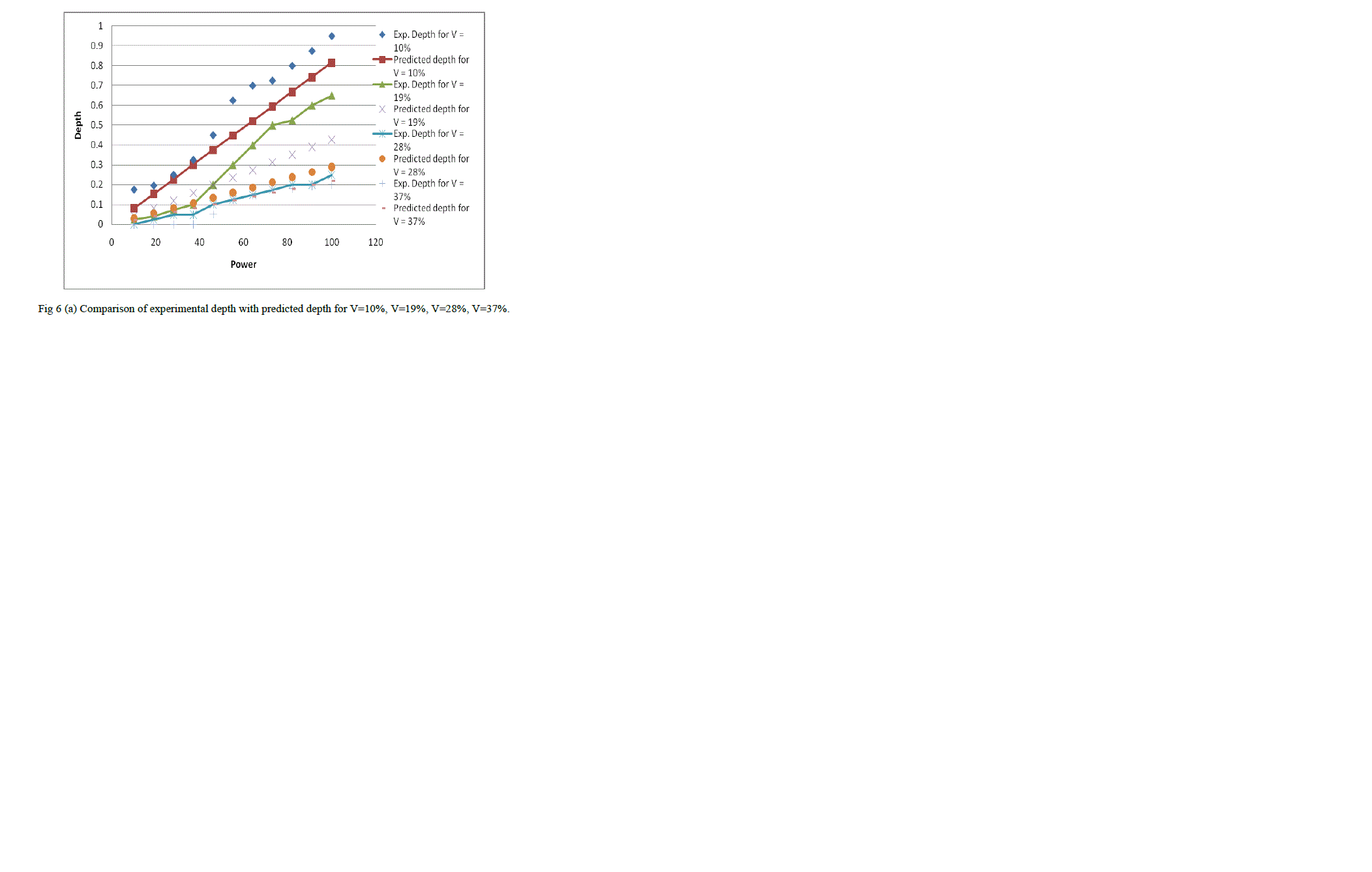 |
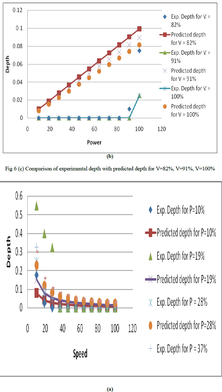
| Fig. 6 shows the variation of experimental depth and predicted depth with power. Scattered points indicates experimental values of depth whereas straight line with points shows predicted values of depth. From the figure, it can be seen that for speed = 10%, few experimental points fall near to predicted points while other are away but on the same side which indicates unidirectional error in the readings. Similar observations are found for other values of speeds which are shown in figure below. Similarly, using the same equation (12), the comparison of experimental depth with predicted depth by varying speed for different power combination is shown in the Fig 7 (a,b.c). |
 |
 |
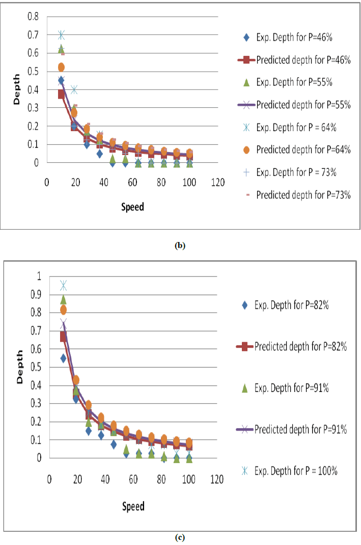 |
| Fig 7 Comparison of experimental depth with predicted depth for P=10%, P=19%, P=28%, P=37% (b) P=46%, P=55%, P=64%, P=73% (c) P=82%, P=91%, P=100% |
| It was observed that the experimental value converges well with the predictive values as average error is within 4.5%. However by variation of speed as low gives slight deviations after 40% of power, speed as medium initiates slight deviation after 60% of power and speed as high initiate slight divergence after 80% of power. The slight deviation is due to variation in material evaporation than the required which ultimately leads to dimensional inaccuracy and this inaccuracy results in error. Whereas for low power, it is observed that the value of error is less due to minor removal of material and also for high speed, it is found that the interaction time between laser beam and workpiece material decreases, hence the thermal energy available at the workpiece surface decreases due to which less removal of the material takes place and ultimately results in error. Thereby, choosing the appropriate values of power and speed, results in less bias and accuracy of the shape is maintained. |
CONCLUSION |
| The experiments carried out during the reported work includes laser cutting of acrylic specimens by varying cutting parameters like Power (P), Speed (V). The set of data obtained was useful in developing a model for predicting depth of cut for single pass cutting for various combinations of speed and power. It was found that depth of cut increases with increase in power whereas depth of cut decreases with increase in speed. The value of average error obtained as 4.5% which shows close convergence of predicted model from the actual one. The variation of predicted model from the actual one may be due to the evaporation of material and getting settled back during the experiment. The variation in depth data may be due to ineffective utilization of blower system. Since the specimens consist of blind holes, the removed material during machining may get settled down before evaporation by the blower and cause uncertainty in data. |
References |
|