ISSN ONLINE(2319-8753)PRINT(2347-6710)
ISSN ONLINE(2319-8753)PRINT(2347-6710)
Devendra Singh1, Dr. Mohd. Suhaib2
|
| Related article at Pubmed, Scholar Google |
Visit for more related articles at International Journal of Innovative Research in Science, Engineering and Technology
This article presents a survey of the various considerations and methods for the kinematic design of gear drives. The gear drive must provide best possible efficiency, reliability of function and service life for the application it designed for. The geometrical shape of the teeth of the gears in mesh not only affects the performance of the gear drive but also the strength of gear tooth significantly. Friction is very significant factor affects the efficiency and wears failure of gears. Friction is also depends on the profile of gear teeth and contact pressure between the surfaces of gear teeth in mesh during the operation of gar drive. Sometimes, the performance of gears in mesh can be improved by providing small modifications in the gear tooth profile. The gear drive must run without interference and having higher contact ratio for its smooth operation. .A good amount of literature available on date dealt with the various methods using various kinematic and geometrical considerations to achieve best possible performance of the gear drive. These methods used few common and few different assumptions giving different results. Therefore the objective of this article is to provide a survey to select a concept for geometric and kinematic design of gear tooth to enhance the performance of any existing gear drive.
Keywords |
| profile, friction, interference, efficiency, contact ratio. |
INTRODUCTION |
| Gears are toothed wheels used to transmit the torque between two parallel, intersecting or nonparallel and nonintersecting shafts at constant angular velocity ratio. The earliest written description are said to have been made by Aristotle in 400 B.C. [1, 2]. The very early use of gears is found in the differential of “South Pointing Chariot” created by Chinese around 2600 B.C. During the 16th to 18th century the mathematics of gear tooth profile and theory of gearing had been established. Since then a lot of advances in the theory of gearing and gear tooth profile has taken place to reach to the modern times gears. Today’s gears are most commonly used means in the form of main or ancillary mechanism for transmitting the power in machines, automobiles, rotorcrafts, turbo-generators load lifting machines, watches etc. In designing of gear drives, the important considerations are reliability of operation, efficiency, service life, load carrying capacity and overall cost. Overall cost includes manufacturing, running and maintenance cost. The gear drive with higher efficiency may result in reduced running cost may cause significant reduction in overall cost having initially higher manufacturing cost. Efficiency of gear drives significantly depends on the frictional losses during the operation especially in low efficiency gear drives. As both the rolling and sliding motion involves in the operation of any gear drive. Friction also affects the life and load carrying capacity of gears especially when scoring is the criterion of failure of gear. The requirement of fuel economy in today’s passenger vehicles, cargo vehicles and rotorcraft due not only to increasing fuel cost but also to environmental concerns made the efficiency of spur and helical gear system an increasingly important research topic. The geometrical profile of gear tooth affects the friction between the mating surfaces as well as interference during the operation of gear drives. Sometimes a combinative profile of conjugate and non-conjugate geometrical profiles reduces the frictional loss and interference free operation of gear drives with a little bit modifications in these profiles. Thus the various approaches and kinematic considerations are reviewed and present in the next section and select an appropriate approach for the further research to undertake by the author for improvement in the design of gear drives. |
II. RELATED WORK |
| As soon as the mathematics and theory of gearing was established during 1450 – 1750 A.D., the generation of conjugate profile was the major research work. Leonard Euler worked out the law of conjugate action in 1754 [1] and in addition to his tremendous contribution to mathematics and mechanics, proposed involute gearing in 1781, that was later found to have a broad application in industry. Cycloidal profile was in use for the tooth profile geometry in older days, but it has become obsolete due to manufacturing difficulties, and involute profile become popular now a day due to its ease in manufacturing. However involute profile suffers from interference. Robert Lipp in 1982 established an equation for determining the number of teeth on the spur pinion and gear with involute teeth, as a function of pressure angle given in equation (3) and (4) for interference free gear drive[4]. Olivier in1842 and Gochman in 1886 developed the basic ideas underlying the conjugation of gear tooth surfaces and their generation. In 1952 Faydor L. Litvin gave the equation of meshing derived on the basis of the concept of the envelope to a family of surfaces that gives the kinematics of manufacture and machine tool settings to generate the conjugate profile [6]. There are several ways proposed in literature [18-24] to prevent the interference in the gear drives with involute profile of gear teeth geometry. The commonly used methods to avoid the interference are, adjusting the pressure angle, removal of material from the interfering zone, using smaller height teeth (stub tooth system), or selecting the appropriate number of teeth on the pinion etc. The pair of gear teeth is subjected to the combination of sliding and rolling motion throughout the line of action except at pitch point, where pure rolling takes place during the operation of gear drive. The sliding motion causes the sliding friction as well as the transmission error in the gear drives. The sliding friction causes the loss of transmission efficiency as well as accelerates the wear of the gear tooth surface. The transmission efficiency as well as wear life can be improved by reducing the friction between the mating gears. Jian Wang, et al. (2010) proposed a preliminary design method for geometry of tooth profile by considering the smaller values of sliding coefficients. The proposed design resulted in reduction in bending as well as contact stress magnitude by 22.06% and 16.77% [39]. The operation of gear drives with involute teeth gears is as smooth as high the contact ratio. For obtaining the higher contact ratio the height of the teeth has to increase that increases the chances of interference. Evgeny Podzharov et al (2003, 2008) proposed the higher contact ratio by using combination of curves as involute and circular arc as tooth profile to achieve contact ratio up to 1.96 by slight increase in addendum [44, 47]. Transmission error causes the inaccurate transmission of motion between the mating gears, and sliding friction causes the loss of power as well as affects the life of the gear tooth surface. Transmission errors can be minimized by providing the addendum modification or by using parabolic transmission error function for designing the geometry of tooth profile [50, 51]. |
III. KINEMATIC CONSIDERATIONS IN GEAR DRIVES |
| The kinematic design of gear drives involves the designing of gear tooth geometry to transmit the rotational power without interference. The following section presents various considerations in the kinematic design of the gear drives. 1. One of the most important characteristics of gear drives is to produce a constant angular velocity ratio during meshing, known as conjugate action (fundamental law of gearing). The fundamental law of gearing states that, the common normal to the tooth profiles at their point of contact and the line of center always intersects at a fixed point. This fixed point is always lie on the line of action and known as pitch point. The pitch point and line of action are shown in Fig.1 as Point P and BC respectively [3, 4]. 2. The kinematics of manufacture and machine tool settings to generate the conjugate profile is given by equation of meshing. The relative velocity “V" between a point on the cutting surface and the same point on the pinion being cut must be perpendicular to the cutting surface normal “n”, for the equation of meshing [5]. |
| Faydor L. Litvin in 1952 gave the equation of meshing derived on the basis of the concept of the envelope to a family of surfaces as given by following equation, where (u,ïÃÂñ ) are the surface parameters, and ïÃÂæ is the generalized parameter of motion [6]. |
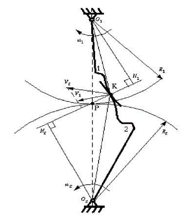 |
| Figure 1, conjugate action of gears, source [3] |
| A relation for the analysis of meshing of two beveloid gears with a prescribed amount of backlash of beveloid gears without considering the interference, undercutting or contact ratio [7]. The equation of meshing for low noise stable bearing contact spiral bevel gear with substantial decrease in the vibration and noise up to 50% [8]. The equation of meshing for involute crossed helical gears which tooth surfaces are in point contact and proposes effective methods of crowning of gear tooth surfaces for conventional helical gear [9]. Investigated the constraint governing equations and the kinematic relationships between the relative velocity and the instantaneous screw axis for spherical gear set and they derived the meshing contour surfaces of spherical gear set with skew axes [10- 11]. Litvin’s concept of limiting curve used to establish the equation of meshing for internal gears without undercutting [12]. The fundamental gearing kinematics applied for establishing an equation of meshing of the elementary planetary gear train consist of pinion with cylindrical tooth [13]. The general theory of gearing is formulated by using just one reference system become easier and straightforward in a computerized procedure even when the motion is quite complex [14-16]. A method of determining contact lines using the concept of surface roll angle to obtain more accurate contact curves [17]. 3. The contact of tooth profiles which are not conjugate is called interference. Referring Fig.2, when CD>AB, the involute tip or face of the driven gear tends to dig out the non-involute flank of the driver, results in the interruption of power transmission and the phenomenon is called interference. This condition can be avoided by providing undercutting in root of flank, stub tooth, adjusting the pressure angle or selecting the appropriate number of teeth on pinion etc., any one alone or in combination. The minimum number of teeth (NP) on the spur pinion to avoid interference and the number of teeth (NG) on largest gear with the interference free pinion is given by following equation (3) & (4), Where k=1 for full depth and 0.8 for stub teeth & ïÃÂæ is the pressure angle. |
 (3) (3) |
 (4) (4) |
| A design technique is proposed for designing interference free mechanism by providing non-overlapping link volume of any link in space with any other link in the range of motion of mechanism. This concept may be used for designing interference free gears [18]. A mathematical relation is established to achieve the conditions of avoiding tip interference by tooth truncation and center distance modification keeping the contact ratio within a satisfactory limit [19]. A method for determining the analytical expression of the limit curve to avoid interference without undercutting in external and internal gear drives [20]. The characteristics of trochoids are discussed and presented a concept of virtual involute to find the intersection point between two trochoids shown |
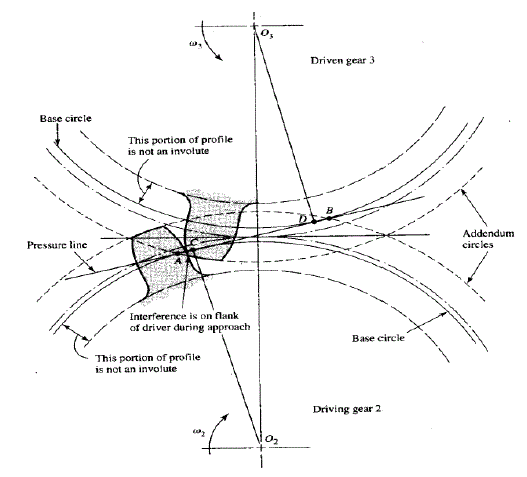 |
| Figure 2 kinematics of meshing of gears, source [4] |
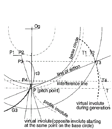 |
| Figure 3 primary and secondary trochoids, source [21] |
| in Fig.3, determine the shape of root fillet to be generated by rack cutter to avoid interference [21]. An expression established for straight conical involute gear tooth for the minimum value of the inner transverse addendum modification coefficient that avoids undercutting of the whole gear tooth [22]. Some kind of tip relief is described for minimizing the interference in gear drives. The effect of interference on wear and on frictional torque by mixed FEM and analytical approach using Fölmer’s equation also presented and found both the size and peak-to-peak friction torque increases with the flank interference [23]. A mathematical model developed for elliptical gears with circular-arc teeth according to gear theory to decreases the design radius of tooth undercutting [24]. Bertrand conjugate surfaces presented for normal circular-arc gears drive for paralleled-axis or intersected-axis drive, for satisfying the non-interference condition automatically, but for other types of gears interference must be checked [25]. 4. There are a number of tooth forms satisfying the law of conjugate action known as conjugate profiles. The geometrical shape of the gear tooth also affects the stress levels, power transmitting capacities and also the size of the gear drive. Olivier (1842) and Gochman (1886) developed the basic ideas underlying the conjugation of gear tooth surfaces and their generation. N.I. Kolchin (1949) applied Gochman’s ideas to develop the geometry of modern gear drives. The researchers suggested a number of various profiles and modified profiles to improve the performance of the gear drive. Involute and cycloidal profiles are well known conjugate profiles [26]. The cycloid profile became obsolete for commercial gears now due to some practical difficulties in producing it, although it is free from interference. The involute profile is easy and economical to produce that made it as the choice of the designers for the gear drives now a day. The shortcoming if any of the involute profile may be overcome by using some non-standard systems of gear tooth. A method of integration of differential equation for the meshing between gears of variable radius to determining the profile of the gear teeth [27]. A mathematical model of gear profile as a combinative curve that comprises a straight line (involute curve) and a circular arc (extended cycloid) [28]. A new geometry of modified helical gears with double crowned pinion and gear tooth surface having the conventional screw involute helicoids proposed in ref. [29]. The kinematic method for synthesis of the spatial gear pair (skew–axes gear pair) helical flanks by using pitch point mathematical model [30]. A deviation function method using non uniform rational B-spline as the deviation function for designing new profiles of non-circular gears [31]. The generating method and a mathematical model of cylindrical gears with curvilinear shaped teeth according to gear theory [32-33]. A concept of elementary gear trains having a pinion with cylindrical tooth-profiles and the profile developed by using parametric form of theory of envelop for a family of surfaces. The pitch radius is replaced by the distance between the gear center and the tooth center as the radius of gears [34]. |
| A method is developed for seeking the optimum conjugate gear tooth profile as per the nature of the service of the gear to render, by solving the differential equations, formulated by considering the conditions for corresponding performance index reaches its optimum value. The method gives better results in terms of tooth flank load capacity and meshing efficiency [35]. A mathematical expression is derived to modify and optimize the gear profile along the line of action to reduce level of noise and rotational vibration, using SISO dynamic system and applying LSM (least square method) [36].A mathematical model is established for generating circular arc-curvilinear teeth gear drive. By selecting of proper radius of curvilinear tooth trace and the radius of circular arc tooth profile of the cutter, can increase the load carrying capacity as well as reduces the contact stresses [37]. It is very difficult to keep the cost of conventional helical gear set low because of tight tolerances and high rigidity in gear housing are required as it is highly sensitive to misalignments & load deflection. A double crowned helical gear derive is presented with tooth form consist of cycloidal curve in the longitudinal direction and a circular arc in the profile direction. The proposed drive is insensitive to axis misalignment and center distance variation [38]. The geometrical design of the gear tooth is proposed on the basis of lower sliding coefficient to reduce the frictional losses [39]. The modelling of the conjugate profiles of gear for kinematic, static and dynamic behaviour of the geared mechanisms is a tedious and time consuming exercise. Many theories are available in the literature to solve this problem and the Litvin’s Theory of Gearing is most widely used. A simple and easy technique is proposed which generally faster (up to six times depending on the problem) than the other existing generic gear theories including the widely used theory of gearing. The gear tooth flank is discretized in infinitesimal involute segments in place of in straight linear segments to obtain a closed non-implicit solution for the calculation of the conjugate profile [40]. The pressure angle function (PAF) is defined as function of pressure angle to the angular displacement of gears to describe and design the geometries and geometric characteristics of meshing tooth profile of planar circular and non-circular gears [41]. |
| 5. Contact ratio is one of the important kinematic parameter affects significantly the performance of any gear drive. Contact ratio signifies the average number of pairs of gear teeth in mesh during a meshing cycle. The higher contact ratio ensures the smooth operation of the gear drive. Contact ratio increases by increasing the addendum of the gear tooth but interference puts a limit on it. Therefore some modification in the tooth profile is required to have higher contact ratio with interference free operation of the gear drive. The tooth profiles of involute bevel gear sets are studied, and compared the contact ratios. He found that the contact ratio of cycloid bevel gear is more as compared to involute bevel gear [42]. A method of designing high contact ratio spur gears using quadratic parametric tooth profiles is proposed in ref. [43]. A gear profile as a combinative curve that comprises a straight line (involute curve) and a circular arc (extended cycloid) may give higher contact ratio. The modified helical gears with double crowned pinion and gear tooth surface having the conventional screw involute helicoids also offers increased contact ratio. The contact ratio can be increased by increasing the number of teeth on the pinion and gear by one and introducing negative profile shift as proposed by Nikalayev and Podzharov [44]. A mathematical model is proposed for modified helical gear with small number of teeth by positive tooth-profile shifted cutting and basic geometry modification causes the increase of gear fillet thickness or undercutting may be reduced. The increase of fillet thickness results in the decrease of gear addendum reduces the contact ratio for the drive [45]. The gear teeth in meshing due to elastic deflection investigated and offers increased contact ratio during operation [46]. The contact ratio about 1.96 can be achieved by slight increment in the addendum height of the standard tooth of the spur gear [47]. |
| 6. Transmission error is the amount of delay of motion between the driving and driven gear of a gear drive. Transmission error is one of the significant causes of vibration and noise in any gear drive. The generation of noise and vibration affects the efficiency of the gear drive adversely. The increased noise and vibration make the gear drive unsuitable for heavy and high speed applications. The properly design or modified profile of teeth of gears may reduce the transmission error in gear drives and result in higher efficiency drives, may be used for high speed applications. The transmission error caused by misalignment in helical gear can be reduced by using modified double circular-arc teeth. Teeth are generated by using the predesigned parabolic function of transmission errors and generated by CNC machine [48]. A spiroid worm-gear drive with modified geometry by modifying spiroid worm is obtained by a combination of profile and longitudinal crowning and reduced level of transmission errors with localized bearing contact [49]. The modified Novikov-Wildhaber helical gear drive with double crowned pinion by used parabolic rack cutter and parabolic transmission errors for achieving lesser value of noise and vibration [50]. A new geometry of tooth surfaces developed by applying double crowning and predesigned parabolic transmission function to lower the transmission error in planetary gears. [51]. The transmission errors investigated in the anti-backlash conical involute gears. It was showed through the FE simulations that the transmission error changes abruptly between the characteristic states for the gear transmission, and if the gear transmission is of a load-balancing type, it has directional properties [52]. The effect of the load on the function of transmission error was investigated and applied predesigned parabolic function of transmission error. The generation of one member of the drive especially pinion modify accordingly and found reduction in the noise and vibration. The loaded gear subjected to elastic deflection increases the contact ratio and reduces the transmission error, caused by misalignment. The effects of machining error, assembly error, and tooth modification (lead crowning and end relief) on transmission errors of spur gears investigated by using FEM. It was found that transmission error increased with the increment in machining errors, assembly error and increased lead crowning and end relief. But the waveform does not change in the latter case, while with the increased machining error the wave form of transmission error changed [53]. By using tooth contact analysis to investigate the combined influence of machine-tool settings for pinion teeth finishing and misalignments of the mating members on load distribution and transmission errors on mismatched spiral bevel gears. The effect of relative position errors of the pinion and gear on tooth contact pressure and on transmission errors can be significantly reduced by optimizing the combination of machine-tool settings for pinion teeth finishing [54]. The genetic algorithm is applied by using micro-geometric parameters like tip and root relief for optimizing the spur gear pair to minimize the noise and vibration. The objective function depends on static transmission error, and it was found that the linear modification is more effective but expansive as compared to quadratic one [55]. Through a computer method used to analyse the static and dynamic transmission errors and found that high contact ratio spur gears having lower static and dynamic transmission errors. A quasi-infinite elastic model composed of springs with stiffness peculiar to the gear presented a general model for the tooth meshing of gears as. A theoretical equation for the transmission error of gears is established and investigated the various factors affecting the transmission error and shown that the amount of transmission error is proportional to the amount of tooth flank deviation [56, 57]. The vibration of gear pair can be reduced through relationship between meshing vibration components and the common gear tooth surface geometries of helical gears with lead crowning or profile crowning to the suitable amount in the design stage [58]. The helical gear drive with double crowning of the tooth form consisting cycloidal curve in the longitudinal direction and a circular arc in the profile direction become insensitive to axis misalignment and transmission error. By imposing total tooth relief, at the tooth tip equal to the deflection of tooth pair under the nominal torque the transmission error can be reduced [59]. Amount of transmission error depends on the amount of deviation of tooth flank from standard one. Therefore during manufacturing the exact tooth forms should be achieved, it is needed to perform the measurement of tooth profile during manufacturing. A Gauge Block Gear (GBG) calibrated by swing round method is used measure the tooth profile. In GBG, the teeth of an ordinary master gear replaced with gauge blocks to allow direct traceability of the chordal tooth thickness and evaluate the commonly used pitch deviations’ measurement uncertainties [60]. The point laser triangulation (PLT) probes enables coordinate measuring machines (CMMs) to take faster, noncontact, accurate measurement of geometry of helical gear profile [61]. A direct method by involute artifact using a laser interferometer for measuring the detailed form of an involute tooth flank precisely [62]. A gear pitch measuring instrument GMI called multiball artifact (MBA) shown in Fig.4. The balls are assumed as gear teeth, calibrated with CMM by adapting the multiple-orientation technique [63]. The schematic view of the double ball artifact (DBA), shown in Fig.5, it can be used as a mean to evaluate the profile measurement accuracy. The center of centering ball is fixed on the rotational axis of the GMI and form checking ball is used to measure the tooth flank of the gear [64]. |
| 7. The magnitude of the stresses at induced in the gear tooth root depends on the nature of loading and mating as well as the cross sectional area of tooth root. The root area depends on the geometrical shape of the tooth. The level of induced stresses may be reduced by appropriate design or modification of the profile of the gear tooth. The high contact ratio spur gears designed by using quadratic parametric tooth profiles with smaller addendum offers lesser root bending stresses as compared as compared to the involute profiles with high contact ratio but the surface contact stresses and wear height indices will increases. Gears with asymmetric tooth, consists of two involutes of different base circles diameter and fillet. This profile enables to increase load capacity, reduce weight, size and vibration level and obtain the minimum bending stress in the gear drive [65]. The reduction in bending stresses can be achieved by using modified geometry of asymmetric involute spur gear using the larger pressure angle on the driving side [66, 67]. A deviation function method using non uniform rational B-spline as the deviation function for designing new profiles offers lower surface contact stresses and increased root bending strength. A spur pinion that is conjugated to a parabolic rack-cutter of face-gear avoids the edge contact due to longitudinally orientation of bearing contact and reduction in contact stresses [68]. The face gear generated by a shaper or grinding worm with rounded top edge reduces bending stresses by 10% approximately [69]. |
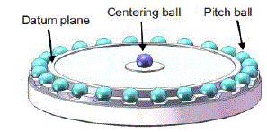 |
| Figure 4, Schematic view of MBA, Source [63] |
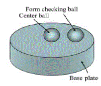 |
| Figure.5, Schematic view of DBA, Source [64] |
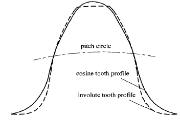 |
| Figure 6, Cosine tooth profile and involute tooth profile, Source: [70] |
| The modified Novikov-Wildhaber helical gear drive with double crowned pinion offers lesser contact and bending stresses. The modified helical gears with double crowned pinion and gear tooth surface having the conventional screw involute helicoids results in lesser magnitude of contact stresses as compared to conventional helical gears. A cosine gear profile consist of a part of non conjugate profile takes the zero line of cosine curve as a pitch circle. The cosine tooth profile is shown in Fig.6, having lower value of sliding coefficient, root bending stress and contact stress as compared to the conventional gear drive [70]. A modified form for the equation of non- conjugate meshing derived from a modified set of generalized equations for profile tangency. These equations reduced to a single scalar equation, resulting in improved solution speed and stability. The numerical solution of theses reduced form of equations by using bisection algorithms to give faster, accurate and stable solution as well as independent of initial value [71-72]. The geometrical design of the gear tooth on the basis of lower sliding coefficient offers increased bending strength as well as lesser value of contact stresses. The bending stress level can be reduced by using the asymmetric tooth with larger root thickness in the section of stress concentration. With the high value of pressure angle on drive side and independent of number of teeth, the bending stress improves about 40% and roughly half of size with high pressure angle on coast side [73]. |
IV. DISCUSSION |
| A review of kinematic considerations in the gear design is presented in this article. Gears are vital power transmitting element in any mechanical system. The primary objective of the application of gear drive is to transmit the power between mating gears at constant velocity ratio as described in ref. [3, 4] without any interference. Interference is described in ref. [4], and methods to eliminate or minimize the condition of interference are proposed various scholars are referred in ref. [18-25]. In ref. [5-17], the various approaches proposed by scholars to establish the equation of meshing. The geometrical shapes of the gear teeth affect the transmission performances significantly as discussed in ref. [35-39]. The transmission performance of any gear drive includes the higher service life, load carrying capacity, efficiency and interference free operation during a meshing cycle. Transmission error is important parameter affects the transmission performance of any gear drive. Higher transmission error may cause the vibration & noisy operation also may cause wear and affects the life. The presence of vibration/noise causes the loss of power in drive itself and reduces the transmission efficiency of gear drives. A number of scholars studied transmission errors and proposed the methods of profile design or generation to reduce or take it to the minimum possible level in the ref.(s) [38,46,49-59]. The transmission error can be reduced by maintaining the accurate shapes of tooth flanks, in the ref. [57-64] various methods and devices to measure the accuracy/errors in shapes of tooth flanks are discussed. The load carrying capacity can be increased by reducing the level of induced bending and contact stresses by proper geometrical design of gear tooth surface as described in ref.(s) [29,31, 38, 39, 43, 65-73]. Every gear drive subjected to relative rolling and sliding velocities in the meshing cycle during operation induces the friction between the gear tooth surfaces in mesh. Friction causes a significant loss in transmission efficiency of the gear drive as well as adversely affects the surface fatigue strength consequently on the load carrying capacity and service life. The sliding coefficients can be reduced to lower the friction by geometrical design of gear tooth profiles as in ref.(s) [45,70]. And a method of designing of gear tooth profile by considering lower value of sliding coefficients in ref. [39]. Every gear drive subjected to relative rolling and sliding velocities in the meshing cycle during operation induces the friction between the gear tooth surfaces in mesh. Friction causes a significant loss in transmission efficiency of the gear drive as well as adversely affects the surface fatigue strength consequently on the load carrying capacity and service life. The sliding coefficients can be reduced to lower the friction by geometrical design of gear tooth profiles as in ref.(s) [45,70]. And a method of designing of gear tooth profile by considering lower value of sliding coefficients is presented by Jian Wang, et al. (2010) in [39]. |
V CONCLUSIONS |
| The objective of this article to study about the kinematic consideration in a gear drive to achieve the maximum possible efficiency in transmission of power. The article includes the various kinematic considerations as equation of meshing, various geometrical shapes (profiles) and ways for the modification in profiles to improve the transmission performance of gear drives. The performance of any gear drive will become better if it is having least friction, transmission error and highest contact ratio along with higher bending and surface fatigue strength. In [39] a method of geometrical design of the gear tooth by considering the sliding coefficients is proposed. An increment of 20% in bending strength was obtained by using the lower value of sliding coefficient analytically. The proposed method in [39] along some profile modification may become very useful in designing the better transmission performance gears as compared to the existing gear drives. The modifications are to be in the direction to achieve the higher contact ratio so that the power can be transmitted smoothly with less noise and vibration. Thus the higher transmission efficiency, load carrying capacity and reliability of operation can be achieved with significant reduction in running cost of the designed gear drive. |
References |
|