ISSN ONLINE(2319-8753)PRINT(2347-6710)
ISSN ONLINE(2319-8753)PRINT(2347-6710)
N.VimalRadha Vignesh1,R.VigneshRam2
|
| Related article at Pubmed, Scholar Google |
Visit for more related articles at International Journal of Innovative Research in Science, Engineering and Technology
Nowadays the power system structure is complicated and the demand is increasing rapidly. In order to minimize the power losses and to reduce power shortage, we go for renewable resources. In This paper, we concentrate on the solar energy, the solar power generation by PhotoVoltaic (PV) arraycombined with the active power filter (APF) has been proposed. In this paper the model is consists of a PV power plant, a DC–DC boost converter, and an active power filter. A novel control approach for the DC–DC converter has been developed in order to extract the maximum power from PV arrays. Also, a novel control approach is based on generalized instantaneous reactive power theory, has been proposed for the active power filter. The simulation results are based on MATLAB/SIMULINK model, the proposed system can provide the power factor correction, harmonic elimination, load balancing, and reactive power compensation and simultaneously inject the maximum power available from the PV array into the grid.
Keywords |
| Renewable resources, PhotoVoltaic (PV) array, active power filter (APF), DC–DC boost converter, reactive power theory, MATLAB/SIMULINK model, power factor correction, harmonic elimination, load balancing, and reactive power compensation. |
INTRODUCTION |
| AllSolar energy has great potential to supply energy with minimum impact on the environment, since solar energy is clean, pollution-free and endless. With the decrease in the price of photovoltaic (PV) modules and the increase in the price of conventional petrochemical fuels, the application of the PV generation system becomes more practical, feasible and achievable[1, 2].PV cells are normally connected together to make up modules, which can be combined into PV arrays as required. Therefore, power electronic converters are an enabling technology that is necessary to convert PV array DC power into usable normal AC power for grid support or supplying loads [3, 4, 5]. Grid-connected PV generation is one of the major development trends of solar energy applications. Moreover, PV grid-connected generation operates during the day and has to stop at night. This affects the stabilization of power system and the utilization of equipment. Therefore, in order to increase the utilization, the PV system can be designed to also provide the function of power quality managements [6]. Also, grid-connected PV system can be used to reduce the peak demand that the utility must satisfy. In this application, the PV system does not require a battery bank, but the power stage remains idle during the night [7]. One drawback of solar energy sources is the need for battery bank for the system to be utilized for a significant percentage of the day. Avoiding adding a battery bank to a PV generation system results in a design, which needs the combine operation with Active Power Filter (APF) to also provide the power factor correction, load balancing, harmonic elimination, reactive power compensation and simultaneously inject the maximum power available from the PV array into the grid [8]. When the solar irradiation is unavailable, then the active power filter can still be utilized to improve the power quality. When the solar irradiation is available, the proposed system can supply the load and simultaneously solve growing problems of harmonics, unbalanced loads and reactive consumption in distribution system [9]. The PV array is interfaced with the utility network via DC–DC boost converters and a three-phase Pulse-Width Modulation (PWM) DC–AC converter, The DC voltage generated by a PV array varies widely and is low in magnitude. Therefore, a DC–DC boost converter is necessary to generate a regulated higher DC voltage for desired converter input voltage. Generally, the grid connectedPV systems extract maximum power from the PV arrays. The Maximum Power Point Tracking (MPPT) technique is usually associated with a DC–DC converter. The shunt APF, which has a DC–AC Voltage Source Converter (VSC) can provide the harmonic elimination, load balancing and power factor correction [10]. Moreover, VSC is employed to interface PV array with utility grid under both on-grid and off-grid operation modes [11]. The DC–AC converter injects sinusoidal current into the grid, and can control the power factor [12]. Therefore, DC– AC converter in grid-connected PV system can have the function of shunt APF. This paper proposes the combined operation of shunt APF and PV grid-connected generation system. The suggested system has been used as shunt APF, when solar irradiation is not available. Also, it can generate the power by PV array and works as APF, when solar irradiation is available [13]. The control strategy of the APF should be able to deliver a preset amount of active and reactive power to the grid or to provide the power factor correction, load balancing, harmonic elimination or reactive power compensation. In this paper, a novel control strategy of the DC–DC converter has been developed, in order to extract the maximum amount of power from the PV array [14]. Also, a new control strategy based on generalized instantaneous reactive power theory has been presented for the active power filter. The generalized instantaneous reactive power theory gives a generalized definition of instantaneous reactive power, which is very easy to calculate and decompose all components, such as fundamental active/reactive power and current, harmonic current and load unbalance [15]. The advantage of the proposed system over the system presented in is the capability of the proposed system to compensate the unbalanced load current, the harmonics and reactive power. The effectiveness of the proposed system has been verified by simulations. The simulation results show that the novel control scheme can adjust the DC energy, compensate the power factor of the utility grid and improve the dynamic behaviour of the grid connected PV system [16]. |
LITERATURE SURVEY |
| The combined operation of the active power filter with the photovoltaic generation system is expressed [1]. The proposed system consists of a PV power plant, a DC–DC boost converter, and an active power filter [2]. A novel control strategy for the DC–DC converter has been developed in order to extract the maximum amount of power from PV arrays [6]. Also, a novel the overall efficiency of photovoltaic (PV) systems connected to the grid depends on the efficiency of direct current (DC) of the solar modules to alternate current (AC) inverter conversion [4]. The requirements for inverter connection include: maximum power point, high efficiency, control power injected into the grid, high power factor and low total harmonic distortion of the currents injected into the grid [7]. An approach to power factor control and reactive power regulation for PV systems connected to the grid using field programmable gate array (FPGA) is proposed. According to the grid demands; both the injected active and reactive powers are controlled [9].A new digital control strategy for a single-phase inverter is carried out. This control strategy is based on the phase shift between the inverter output voltage and the grid in order to control the power factor for a wide range of the inverter output current and consequently the control and the regulation of the reactive power will be achieved. The advantage of the proposed control strategy is its implementation around simple digital circuits [10]. The various compensation strategies for shunt active power filter using a generalized theory of instantaneous reactive power. A general instantaneous vector expression for filter current in terms of active and reactive powers has been derived. The general time domain algorithm for filter reference currents in terms of source powers has been given. It is shown that the algorithm works under balanced and unbalanced source voltages while producing a set of balanced three-phase source currents at a desired power factor [8]. Power-electronics-based zonal direct current (dc) power distribution systems are being considered for sea and undersea vehicles. The stability of the dc power-electronics-based power distribution systems is a significant design consideration because of the potential for negative-impedance-induced instabilities. In this paper, the dynamic properties and control of a buck converter feeding a downstream dc–dc converter are studied [13]. The controller in this system combines an instantaneous current feedback loop using hysteresis with a proportional–integral (PI) algorithm to regulate the output voltage of the converter. Based on a large-signal-averaged model of the converter, the stability-in-large around the operation point is presented. The complete analysis is carried out considering a buck dc–dc converter operating with a constant power load (CPL). Simulations and experimental results are provided to verify the analysis [16]. |
RENEWABLE ENERGY SOURCES |
| True renewable energy sources are energy supplies that are refilled by natural processes at least as fast as we use them. All renewable energy comes, eventually, from the sun. We can use the sun directly (as in solar heating systems, solar PV systems) or indirectly (as in wind power, hydroelectric power, and power from biomass fuels). Thus the Renewable energy sources plays an important role in electric power generation. |
| Solar Energy |
| Solar energy comes directly from the power of the sun and is used to produce electricity, to produce heat, and for light. Solar's contribution to heating and lighting is very much larger. Solar-electric power can be produced by power plants using the sun’s heat (solar thermal) by photovoltaic (PV) technology, which converts sunlight directly into electricity using solar (PV) cells. PV technology is more practical and used for residential purpose. |
| The best-known method utilizes sunlight is acting on photovoltaic cells to produce electricity. Flat plate versions of these can readily be mounted on buildings without any visual interruption or requiring special support structures. A solar photovoltaic system converts sunlight into electricity. The basic device of a photovoltaic system is photovoltaic cell. Cells may be grouped to form panels or modules. Panels can be grouped to form large photovoltaic arrays. The term array is usually employed to describe a photovoltaic panel (with several cells connected in series and/or parallel) or a group of panels. |
| Grid-connected PV systems interface directly with your electric utility connection and allow for excess solar generation to be put back on the grid. When the PV system is not meet the consumption demand then the consumer will receive electricity from the grid. |
| Grid-connected systems with battery storage work like ordinary grid-connected systems, but the battery storage allows you back up capability in case of a power outage. The stand-alone systems appropriate in situations where there is no electric service to begin with. Independent systems require battery storage to provide power at night and in cloudy weather. |
| Wind Energy |
| Wind energy generation has been noted as the most rapidly growing technology; being one of the most costeffective and environmental friendly mean to generate electricity from renewable sources. The increasing penetration level of wind energy can have a significant impact on grid, especially under abnormal conditions. Wind turbines produce electricity by using the power of the wind to drive an electrical generator. |
| Fuel Cells |
| fuel cell is an alternative energy device, but it is not necessarily a renewable energy device. It is only renewable if the source of the fuel used is renewable. A fuel cell is an electrochemical device, like a battery in that it converts the energy from a chemical reaction directly into electricity and heat. But unlike a battery, which is limited to the stored chemicals within, a fuel cell has the capability of generating energy as long as fuel is supplied. Currently produced fuel cells combine hydrogen and oxygen without combustion to produce electricity. The oxygen comes from the air, while the hydrogen can either be produced from water (using electricity) or extracted from fossil fuels. |
| Geothermal Energy |
| Geothermal energy tends to be relatively diffuse, which makes it difficult to tap. Geothermal heat is concentrated in regions associated with the boundaries of tectonic plates in the earth’s crust. |
| There are four types of geothermal resources: |
| • Hydro thermal |
| • Geo pressured hot dry rock |
| • Magma |
| Biomass |
| Biomass resources suitable for energy production covers a wide range of materials, from firewood collected in farmlands and natural woods to agricultural and forestry crops grown specifically for energy production purposes. It includes timber processing residues, solid municipal waste (SMW) and sewage, aquatic flora, etc. Biomass can be divided into four subcategories: |
| • Wood, logging and agricultural residue |
| • Animal dung |
| • Solid industrial waste |
| • Landfill biogas. |
MODELING OF PHOTOVOLTAIC ARRAYS |
| A. Ideal photovoltaic cell |
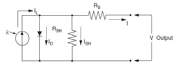
| In Figure 1 shows the equivalent circuit of the ideal photovoltaic cell. The basic equation from the theory of semiconductors that mathematically describes the I-V characteristic of the ideal photovoltaic cell is: |
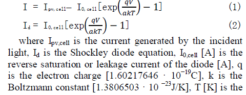 |
| temperature of the p-n junction, and a is the diode ideality constant. |
 |
| B. Modelling the photovoltaic array |
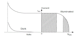
| The basic equation (1) of the elementary photovoltaic cell does not represent the I-V characteristic of a practical photovoltaic array. Practical arrays are composed of several connected photovoltaic cells and the observation of the characteristics at the terminals of the photovoltaic array requires the inclusion of additional parameters to the basic equation. |
 |
| A Maximum Power Point Tracker (MPPT) technique is used for extract the maximum power from the solar PV module and transfer that power to the load. A dc/dc converter(step up/step down) serves the purpose of transferring maximum power from the solar PV module to the load. |
ACTIVEPOWER FILTER |
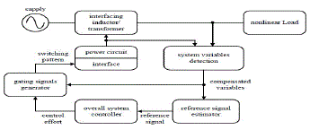
| Duetoremarkablegrowth in power electronics makestheuseof activepower filters(APF)as the dynamicsolutionformitigationofharmonics.Thefundame ntal principleofAPFistoutilizeadvancesinpowerelectronicsswi tchestoproduceequal andoppositecurrentssignalsthatcanceltheharmoniccurre ntsfromthenonlinear loads.Howeverthehighorderharmonicsarenotfilteredeffe ctivelybyusing digital methods.This isbecauseof thesamplingratelimitationforimplementationofhardwar e in real-time application. Moreover, the APF application with the use of fast switching transistors(i.e.MOSFETs, IGBTs) causesswitching frequency noise to appear in the compensated source current. Additional filtering isrequired to minimizethisswitchingfrequencynoisewhichcauses interferencewithothersensitive equipments. |
| The conceptof APF has been proposed and developed by so many researchers.Inthis APFfiltering ofharmonicsisdividedbetweenthetwofilters. Lowerorderharmonicsarecancelled by theAPF,whilethehigherorderharmonicsare eliminatedthrough high pass filters. The main objective APF is to improve the filtering performance of highorder harmonics while providingacosteffectiveloworder harmonic suppression. |
 |
| Activepowerfilters canbe classified based on thefollowingcriteria: |
| Power ratingand speed of responserequired incompensated systems; |
| Power-circuitconfiguration and connections; |
| ` System parameters tobe compensated; |
| Control techniques employed; and |
| Technique usedfor estimatingthe reference current/voltage. |
PROPOSED SYSTEM |
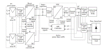
| The proposed configuration of APF and gridconnected PV generation system is shown in Figure 4. The PV power plant consists of two PV arrays connected in parallel. The DC–DC boost converters drain the energy from PV arrays and feed the DC bus capacitor based on MPPT control method. In this paper, the DC bus voltage (DC–DC converter output) is Vdc= 300 V. The DC bus is connected to a bi-directional six-switch current controlled VSC, with neutral clamped DC capacitors. Through this converter, the energy, generated by the PV arrays is transferred to the three phase utility grid (400 V/50 Hz) or the AC loads. An LC filter has been used at the output of VSC to filter the switching frequency harmonics. In this paper, the filter inductor is equal to 2 mH and the filter capacitor is equal to 3kvar. The AC loads are nonlinear and unbalanced. |
| A novel control strategy for the DC–DC converter has been developed in order to extract the maximum amount of power from the PV array. Also, a novel control strategy, which is based on generalized instantaneous reactive power theory, has been proposed for the active power filter. The proposed control scheme for the active power filter is designed to keep this DC bus voltage within a specified limit (i.e., ±5%). Also, this converter controller adjusts the active and reactive power delivered to the utility grid. However, the proposed system, based on novel current controller, can provide the power factor correction, load balancing, harmonic elimination, reactive power compensation and simultaneously inject the maximum power available from the PV array into the grid. Super-capacitors are connected to the DC bus to provide energy storage capability under different operation modes. |
 |
| POWER MANAGEMENT OF PROPOSED SYSTEM |
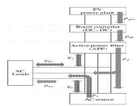
| Power management strategy of AC–DC converter provides suitable power transfer and regulation between AC source and active power filter. Figure 5 shows the ideal active and reactive power flow of PV power plant. |
 |
SIMULATION RESULT AND DISCUSSIONS |
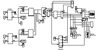 |
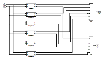
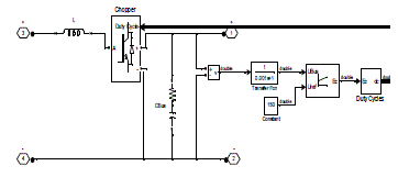
| Simulation model of PhotoVoltaic (PV) array with active power filter block and different types of loads is shown in Figure 6, and Figure 7 shows the Simulation model of solar cell. |
 |
 |
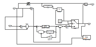
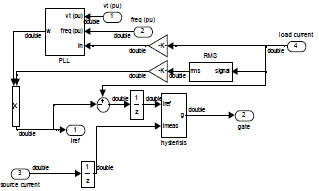
| Simulation model of Active Power Filter blocks are shown in the Figure 11 the Phase Locked Loop (PLL) is feedback with hysteresis control to produce the gate signal for the inverter. |
 |
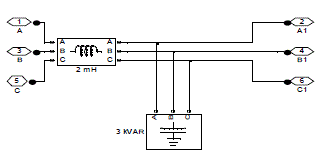 |
| The output of the Active Power filter is provide a reference signal to the VSC inverter which is used here IGBT inverter is shown in the figure 15 The control of inverter gate pulses by using APF for grid connected solar PV system the outputs are shown in the figures 16 and 17 for non-linear load and unbalanced loads. |
 |
 |
CONCLUSION |
| A detailed simulation model of the PhotoVoltaic Array with Active Power Filter is implemented in MATLAB / SIMULINK using SIMPOWER Systems library is proposed in this paper, control system for combined operation of active power filter with PV generation system in grid. This system aids to supply a constant power to the grid. The APF is the intermediate device which is used to maintain the level power supplied to the grid. The dynamic model of PV modules and its power electronic interfaces are modelled, too. Also, a novel control strategy for active power filter is suggested, the current and DC voltage controllers are used to transfer the PV power and synchronize the output converters with the grid. The controller designs for different operation modes of active power filter are studied. The novel control scheme, which is based on generalized instantaneous reactive power theory, is used to control the active and reactive power delivered from the PV generation system to the grid. The simulation results, carried out by MATLAB/SIMULINK software tool, show the effectiveness of the suggested control systems in grid-connected mode. |
ACKNOWLEDGMENT |
| The authors are grateful to the principal and management of K.L.N college of Engineering, Sivagangai for providing all facilities for the research work. |
References |
|