ISSN ONLINE(2319-8753)PRINT(2347-6710)
ISSN ONLINE(2319-8753)PRINT(2347-6710)
| Gurumoorthy and Thirunavukkarasu Electrical and Electronics Engineering, A.M.S Engineering College, Namakkal, Tamilnadu, India |
| Related article at Pubmed, Scholar Google |
Visit for more related articles at International Journal of Innovative Research in Science, Engineering and Technology
In recent year various control strategies have been applied to power converters. DC-DC converter such as Buck type, Boost type, Buck-Boost type have been widely used in traditional industrial application, e.g., uninterruptible power supply (U.P.S),power system, dc motor drive, telecommunication equipment, etc. In the conventional method, Fuzzy control scheme is designed for the voltage tracking of a DC-DC Boost converter. The main draw back of only used Fuzzy logic control switching frequency will not constant on during load condition. AFNNC could be introduced. However, the computation cost is much higher than conventional system. In the proposed method presents an Adaptive Neuro – Fuzzy Inference System (ANFIS) control scheme is designed for the voltage tracking control, Harmonic reduction & current control. Then, the Total Sliding Mode Control (TSMC) strategies are introduced to developed for enhancing system robustness during the transient period .The output of the AFNNC scheme can be easily supply to the duty cycle of the power switch in the boost converter without strict constrains on control parameters selection in conventional control strategies.
Keywords |
| Boost converter, fuzzy neural network (FNN), Lyapunov stability theorem, total slidingmode control (TSMC), voltage tracking control. |
INTRODUCTION |
| Nowadays, clean energies without pollution, such as fuel cell, wind energy, photovoltaic, etc., have been rapidly promoted in order to protect the environment. Due to the electric characteristics of clean energies, the generated power is critically affected by the climate, and the output voltage is easily influenced by load variations. |
| Thus, it is essential to have a DC–DC converter as the output stage of the clean energy to provide a stable output voltage. The boost converter, also known as the step-up converter, is the basic dc–dc converter configuration with an output voltage higher than its input voltage, and it is also often used as the first stage of the clean energy power system to generate a higher regulated dc voltage for the later inverter utilization. From the control point of view, the fundamental control frame for a boost converter is challenging because it is a bilinear system and also a non minimum phase system with respect to the output to be controlled. The bilinear system means the model of the boost converter with a bilinear term, which is the product of the duty cycle and the state. For the control design in the state space, the system stability can only be guaranteed against small perturbations from the equilibrium points of both state and input variables of the original system. |
| The presence of the right-hand-plane zero complicates the control design and, concurrently, limits the available bandwidth for stable operation of the converter. In recent years, various control strategies have been applied to power converters. In utilized a specific linearized technique around the equilibrium point to approximate the whole nonlinear system and used a simple analog circuit to implement this controller. |
BLOCK DIAGRAM |
| The following Figure shows the overall block diagram |
 |
DC-DC CONVERTERS |
| A DC to DC converter is a device that accepts a DC input voltage and produces a Dc output voltage. Typically the output produced is at a different voltage level than the input. In addition, DC to DC converters are used to provide noise isolation power bus regulation; etc. DC-DC converters are mainly classified into four topologies. They are |
| • Buck converter |
| • Boost converter |
| • Buck boost converter |
| • Cuk converter |
BUCK BOOST CONVERTER |
| Two different topologies are called buck– boost converter. Both of them can produce an output voltage much larger (in absolute magnitude) than the input voltage. Both of them can produce a wide range of output voltage from that maximum output voltage to almost zero. The inverting topology – The output voltage is of the opposite polarity as the input buck (step-down) converter followed by a boost (step-up) converter – The output voltage is of the same polarity as the input, and can be lower or higher than the input. Such a non-inverting buck-boost converter may use a single inductor that is used as both the buck inductor and the boost inductor. |
| The buck–boost converter is a type of DC-to- DC converter that has an output voltage magnitude that is either greater than or less than the input voltage magnitude. It is a switched-mode power supply with a similar circuit topology to the boost converter and the buck converter. The output voltage is adjustable based on the duty cycle of the switching transistor. One possible drawback of this converter is that the switch does not have a terminal at ground; this complicates the driving circuitry. |
| Also, the polarity of the output voltage is opposite the input voltage. Neither drawback is of any consequence if the power supply is isolated from the load circuit (if, for example, the supply is a battery) as the supply and diode polarity can simply be reversed. The switch can be on either the ground side or the supply. |
 |
Principle of operation |
| The two operating states of a buck–boost converter: When the switch is turned-on, the input voltage source supplies current to the inductor, and the capacitor supplies current to the resistor (output load). When the switch is opened, the inductor supplies current to the load via the diode D. The basic principle of the buck–boost converter is fairly simple While in the On-state; the input voltage source is directly connected to the inductor (L). This results in accumulating energy in L. In this stage, the capacitor supplies energy to the output load. |
| • While in the Off-state, the inductor is connected to the output load and capacitor, so energy is transferred from L to C and R. |
| • Compared to the buck and boost converters, the characteristics of the buck– boost converter are mainly, Polarity of the output voltage is opposite to that of the input. |
| • The output voltage can vary continuously (for an ideal converter). The output voltage ranges for a buck and a boost converter are respectively 0 to inf. |
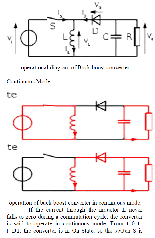 |
| closed. The rate of change in the inductor current (IL) is therefore given by, During the Off-state, the switch S is open, so the inductor current flows through the load. If we assume zero voltage drop in the diode, and a capacitor large enough for its voltage to remain constant, the evolution of IL is: As we consider that the converter operates in steady-state conditions, the amount of energy stored in each of its components has to be the same at the beginning and at the end of a commutation cycle. This in return yields that From the above expression it can be seen that the polarity of the output voltage is always negative (as the duty cycle goes from 0 to 1), and that its absolute value increases with D, theoretically up to minus infinity as D approaches 1. Apart from the polarity, this converter is either step-up (as a boost converter) or step-down (as a buck converter). This is why it is referred to as a buck– boost converter. |
Discontinuous Mode |
| In some cases, the amount of energy required by the load is small enough to be transferred in a time smaller than the whole commutation period. In this case, the current through the inductor falls to zero during part of the period. The only difference in the principle described above is that the inductor is completely discharged at the end of the commutation cycle. Although slight, the difference has a strong effect on the output voltage equation. It can be calculated as follows During the off-period, IL falls to zero after δ.T Using the previous equation, δ is Therefore, the output voltage gain can be written as: Compared to the expression of the output voltage gain for the continuous mode, this expression is much more complicated. Furthermore, in discontinuous operation, the output voltage not only depends on the duty cycle, but also on the inductor value, the input voltage and the output current. |
FUZZY LOGIC CONTROLLER |
| A fuzzy control system is a control system based on fuzzy logic—a mathematical system that analyzes analog input values in terms of logical variables that take on continuous values between 0 and 1, in contrast to classical or digital logic, which operates on discrete values of either 1 or 0 (true or false respectively). Fuzzy logic has the advantage that the solution to the problem can be cast in terms that human operators can understand, so that their experience can be used in the design of the controller. This makes it easier to mechanize tasks that are already successfully performed by humans. |
THE ROLE OF FUZZY SYSTEMS IN CONTROL |
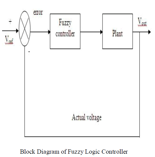
| Regarding a fuzzy system as either an approximate reasoned or functional approximate, it can be utilized in various ways in control systems. The block diagram of FLC is shown in Figure. Instead of directly issuing the control signals, the function of fuzzy system lies in monitoring a low level direct controller by outputting appropriate parameters to be used by the direct controller. The decision taken by the supervisor can be based on the current control performance or the operating conditions depending on the control strategies employed in the system. By treating fuzzy system as a representative model of the controller plant, third usage of the fuzzy system can be found, which is to place it into the various model based control structures found in traditional model. |
 |
DESIGN FACTORS OF FUZZY CONTROLLER |
| The design of a fuzzy logic controller needs the selection of control elements and parameters as scaling factors for input/output signals, a set of rule base, fuzzification and defuzzification methods and operation for the fuzzy reasoning, which include an implication operation, a compositional operation and aggregation operations of antecedents and consequents. The performance of the FLC heavily relies on the configuration of these factors as shown in Figure. |
FUZZIFICATION |
| In a fuzzy control system, the measurement of the input signal is interpreted as a fuzzy singleton. According to the type of fuzzy reasoning, the linguistic variables can be fuzzified in two ways. In the mamdani-type fuzzy inference system, both the input and output linguistic variables will take fuzzy variables as values. In sugeno-type generally zero order fuzzy inference system, the input linguistic variables are fuzzified as fuzzy variables, while the output linguistic variables take fuzzy singletons as values. Fuzzy variables are defined by membership functions (MF) and characterized by shapes, position and width or whole overlap. |
| The number of the fuzzy variables that a linguistic variable can take is known as fuzzy partition and determines the control granularity obtainable from a FLC. A trial and error based on operators experience and engineering knowledge is extensively employed in the choice of MFs. Despite ad hoc approaches for MFs selection, some guidelines exist. In general, for the sake of computational efficiency, efficient use of the computer memory and performance analysis, the MFs are required to have uniform shapes, parameters and function definition. Likewise, the number of the MFs determined by fuzzy partitions is a trade-off between adequate approximation and available memory space. J.V.D. Oliveira suggested that the number of fuzzy variables that a linguistic variable can take should be between 5 and 9. The fuzzification should cover the entire universe of discourse, and there exists a fuzzy number to represent the fuzzy variable “around zero”. As for a certain shape of a membership function, narrower membership functions, despite superiority in faster response and lower steady state error, may incur larger oscillation, and thus the system will be unstable especially in noisy environment. Since the two MF shape match humans intuition and posses’ computation simplicity, they will be kept on in this work. Within the universe of discourse U= [-1, 1]. |
SCALING FACTOR |
| The scaling factors (SF) determined by the plant and actuator are used to normalize different range of input/output signals into the universe of discourse [- 1, 1] and thus can generalize and facilitate the design and configuration of the fuzzy controller. However, unsuitable SFs for the input/output signals can worsen transient and steady-state responses, while the scopes of input/output signals, as the scaling factors, are safe but conservative. |
DEFUZZIFICATION |
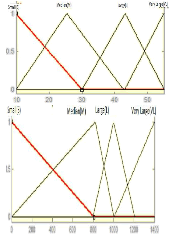
| Defuzzification is for the aggregation of the D from all rules using center of area, Based on the engineering and stand operation knowledge presented in the forthcoming simulation will be conducted based on a set of intuitively chosen fuzzy variables. Four fuzzy variables are set for output, i.e Small , Median, Large and Very Large . Based on the fuzzy variables selected the observation of the behavior of human operators and trial and error, the fuzzy rule base that can ensure the stability and steady state precision. |
FUZZY MEMBERSHIP FUNCTIONS |
| The proposed rule for the Fuzzy Logic Controller the two inputs are Voltage Current |
 |
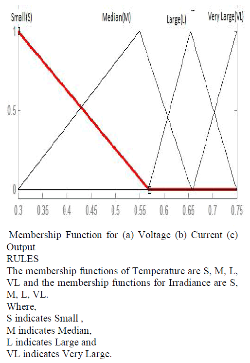 |
| The formulated rules are |
| 1. If V is Small and I is Small, then D is Small. |
| 2. If V is Median and I is Small, then D is Median. |
| 3. If V is Large and I is Small, then D is Median. |
| 4. If V is Very Large and I is Small, then D is Small. |
| 5. If V is Small and I is Median, then D is Median. |
| 6. If V is Median and I is Median, then D is Median. |
| 7. If V is Large and I is Median, then D is Large. |
| 8. If V is Very Large and I is Median, then D is Median. |
| 9. If V is Small and I is Large, then D is Large. |
| 10. If V is Median and I is Large, then D is Large. |
| 11. If V is Large and I is Large, then D is Large. |
| 12. If V is Very Large and I is Large, then D is Very Large. |
| 13. If V is Small and I is Very Large, then D is Very Large. |
| 14. If V is Median and I is Very Large, then D is Very Large. |
| 15. If V is Large and I is Very Large, then D is Very Large. |
| 16. If V is Very Large and I is Very Large, then D is Very Large. |
ADAPTIVE NEURO FUZZY INTERFACE SYSTEMS (ANFIS) |
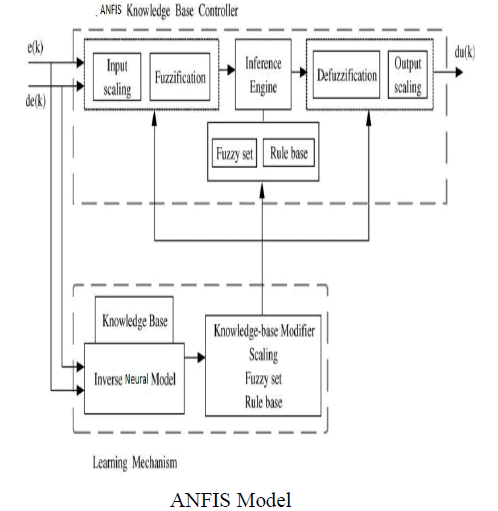
| As we have already seen, fuzzy systems present particular problems to a Developer Rules. The if-then rules have to be determined somehow. This is usually done by ‘knowledge acquisition’ from an expert. It is a time consuming process that is fraught with problems. Membership functions. A fuzzy set is fully determined by its membership function. This has to be determined. If it’s Gaussian then what are the parameters? The ANFIS approach learns the rules and membership functions from data. |
| ANFIS is an adaptive network. An adaptive network is network of nodes and directional links. Associated with the network is a learning rule for example back propagation. It’s called adaptive because some, or all, of the nodes have parameters which affect the output of the node. These networks are learning a relationship between inputs and outputs. Adaptive networks cover a number of different approaches but for our purposes we will investigate in some detail the method proposed by Jang known as ANFIS. The ANFIS architecture is shown below. The circular nodes represent nodes that are fixed whereas the square nodes are nodes that have parameters to be learnt. |
ANFIS MODEL |
 |
SIMULATION RESULT- WAVE FORM |
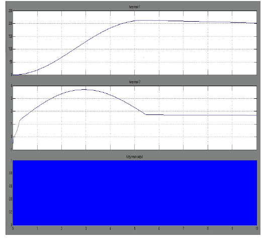
AFNIS INPUT AND OUTPUT |
 |
MOTOR OUTPUT |
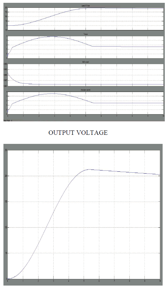 |
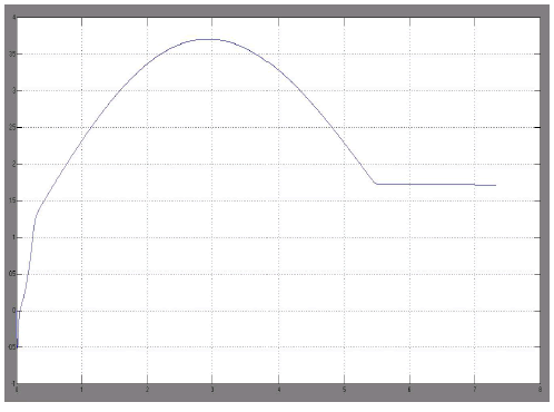
OUTPUT CURRENT |
 |
CONCLUSION |
| The overall performance of the system is improved using an ANFIS controller (TSMC Technique). The proposed system using ANFIS controller can provide maximum power generation due to system, better harmonic reduction (THD), better voltage control and current control. |
| This system tracks out the maximum power in order to meet the power demand. ANFIS controller along with Total Sliding Mode Control technique (TSMC) technique provides a better tracking of power. |
ACKNOWLEDGEMENT |
| We elucidate the successful completion of our project on “NEURO FUZZY SLIDING MODE CONTROL TECHNICQUE FOR VOLTAGE TRACKING IN BOOST CONVERTER”. We put forth this accomplishment upon the feet of almighty for the best owing his blessing and grace which enabled us in the completion of our project. We express our deep dedicated thanks to our management for the tremendous support and inspiration for the successful completion of project. |
References |
|