ISSN ONLINE(2319-8753)PRINT(2347-6710)
ISSN ONLINE(2319-8753)PRINT(2347-6710)
| T. M. Yesansure1, T. G. Arora1 Dept. of Electrical Engineering, Ramdeobaba College of Engineering and Management, Nagpur, Maharashtra, India |
| Related article at Pubmed, Scholar Google |
Visit for more related articles at International Journal of Innovative Research in Science, Engineering and Technology
This paper describes the development of quadrilateral distance relay characteristic for the protection of high voltage line using numerical technique. The characteristic of the relay is generated by the software designed in Visual Basic 6. The software estimates the magnitude of reactance and resistance by using differential equation principle. The analog voltage and the current signal are applied to the computer through Advantech Automation device. The software samples the input analog signals and estimates impedance for characteristic development. The characteristic of the developed numerical relay is adoptive with a provision for changing the relay parameter.
Keywords |
| Distance Relay, Protection of Transmission Line, Relay Software , Usb4711/a |
INTRODUCTION |
| Modern power system is a large interconnected network with costly electrical installations operating continuously to cater the electrical power demand. A power system is designed to generate electric power in sufficient quantity, to meet the present and estimated future demands of the users in a particular area, to transmit it to the areas where it will be used and then distribute it within that area, on a continuous basis. To ensure the maximum return on the large investment in the equipment, which goes to make up the power system and to keep the users satisfied with reliable service, the whole system must be kept in operation continuously without major breakdowns. This can be achieved by foreseeing any possible effects or failures that may cause long-term shutdown of a system, which in turn may take longer time to bring back the system to its normal course. The main idea is to restrict the disturbances during such failures to a limited area and continue power distribution in the balance areas. Special equipment is normally installedto detect such kind of failures (also called „faultsâÃâ¬ÃŸ) that can possibly happen in various sections of a system, and to isolate faulty sections so that the interruption is limited to a localized area in the total system covering various areas. The special equipment adopted to detect such possible faults is referred to as „protective equipment or protective relayâÃâ¬ÃŸ. |
II. PROTECTION OF TRANSMISSION LINE |
| In the transmission line protection, the use of distance relays has found to be the most feasible and effective as compared to the other type of protection such as current actuated relay (over current relay). The over current relays are principally dependants on only one actuating quality which is current. There are some parameters in transmission line like line resistance, source impedance, types of faults, fault location etc which affects the current measured by relay. This leads to unsatisfactory performance of over current relay. On the other hand distance relay being actuated by two quantities, comparatively gives much better performance by taking care of all such factors. There are three types of distance relays namely reactance relay, impedance relay and mho relay. But performance of these relays gets affected by factors like power swing, arc resistance. The quadrilateral distance relay is quite better option for the protection of transmission line as it covers minimum area in R-X diagram and it is closer to ideal distance relay characteristic. |
III. IDEAL DISTANCE RELAY CHARACTERISTIC |
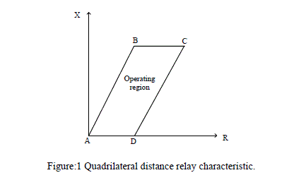
| The ideal characteristic of distance relay will be one thatâÃâ¬ÃŸs takes care of arc resistance throughout length of a line and occupies minimum area in the R-X diagram, hence least affected by power swing. Assuming the arc resistance isconstant throughout the line length. The ideal characteristic in R-X diagram will be a Quadrilateral as shown in Fig.1 Hence Quadrilateral is the ideal distance relay characteristic. It is non-conventional distance relay characteristic.Numerical method is the best method to design relay due to following advantages: |
 |
| 1. It require minimum hardware, hence it is compact, economical, & reliable. |
| 2. Characteristic does not change with time and temperature. |
| 3. It is programmable hence flexible. |
| 4. It offers a great flexibility in terms of onsite changes in the characteristic. |
| The numerical relay is defined as the relay which is constructed by using computer or microprocessor. It is generally made of following components |
| 1. Sample and hold circuit |
| 2. Anti-aliasing filter |
| 3. Multiplexer |
| 4. A to D converter |
| In the numerical relay the analog signals from CT & PT are processed through the series of hardware blocks and finally supplied to the computer/processor in a digital form where the software algorithm processes the digital signal and takes decision about the trip signal. Fig 2 shows a block diagram of numerical relay. |
 |
| As shown in the Fig.2, VR and IR are the relay voltage and relay current respectively. Both of these signals are supplied to the computer through hardware. The hardware part mainly consist of USB4711/A. This is an automation module that has been used in this project to send the real time voltage and current signals to the computer. USB 4711A samples the voltage and current signal, convert it into digital form and send it to computer where software process these signals, computes the value of reactance and resistance and accordingly takes decision about the trip signal for circuit breaker. All the research and analysis done on the quadrilateral distance relay, there are some possible errors that mostly occur during the acquisition i.e. while reading the voltage and current signals in the computer/microprocessor from the outside world. Because the researcher have used electronics based hardware to read data from the PT and CT, circuit used by the researchers, are Op-amp and transistor based circuits and even larger in size. The microprocessor used by the author is of 8 bit which is slow as far as requirement of relay is concerned .Such kind of hardware introduces error in the estimated value of impedance if the input signal contain transient or harmonic component. This paper presents an application of Since, Advantech data acquisition device USB4711/A which has a high level of accuracy of data conversion and high speed data sampling capability to overcome all such problems. |
IV. USB4711/A (ADVANTECH AUTOMATION MODULE) |
| The Advantech USB-4711A is a powerful data acquisition (DAS) module for the USB port. It features a unique circuit design and complete functions for data acquisition and control. As mentioned in chapter 1; in order to generate numerical quadrilateral distance relay characteristic it is required to read real time analog relay voltage and current signals by the computer. The data acquisition device USB 4711/A is used in the project to accomplish this task. This device samples the input signals, converts the signals into digital form and provides the magnitude of the signals in digital and analog form to the computer. Since this device has output channel, the same device is used for issuing the trip signal generated by the relay software. This device has some unique features for data acquisition which are as follows: • 16 single-ended/ 8 differential or combination analog input channels. |
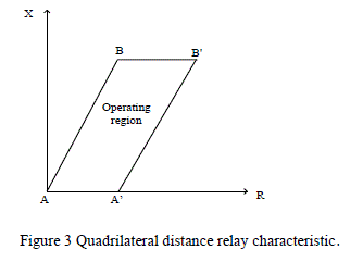
| • 12-bit resolution A/D converter. • 8 digital input & 8 digital output channels (TTL Level). • 2 analog output channels. • Onboard 1K samples FIFO buffer for AI channels. • Removable on-module wiring terminal. • Supports high-speed USB 2.0. • Auto calibration function. • Hot swappable. USB-4711A is equipped with plug-in screw-terminal connectors that facilitate connection to the module without terminal boards or cables the quadrilateral distance relay characteristic consists of four straight lines as shown in Figure3. The positive torque region is the region covered by all the four lines i.e. quadrilateral ABBâÃâ¬ÃŸAâÃâ¬ÃŸA. If the impedance seen by the relay is inside the operating region, then relay trips. Each of these lines can be defined by an equation given by; |
| LineAB: X=m1*R(1) |
| LineBB: X=constant(2) |
| LineAâÃâ¬ÃŸBâÃâ¬ÃŸ:X=m2*R+C(3) |
| LineAâÃâ¬ÃŸA:X=0(4) |
| Where, m1 is the slope of the line AB; m2 is the slope of the line AâÃâ¬ÃŸBâÃâ¬ÃŸ and C is the constant. |
 |
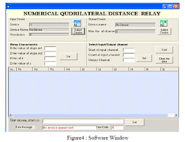
| Hence during fault if inductance and resistance (R and L) up to the fault point are known, the trip condition can be decided. In this project, differential equation based sampling [1] method is used for calculating the impedance of the line which required for the development relay characteristic. A. Relay Software The software for the development of quadrilateral distance relay characteristic is designed by a programming language Visual basic 6. Functioning of automation device USB4711/A can be controlled by assembly languages like Visual C++, Visual Basic, Delphi, and C++ Builder. The software is developed in VISUAL BASIC 6. How the software works? The developed software, samples (reads) two analog inputs corresponding to voltage and current from analog input channel of USB4711/A with a sampling window of four samples. Then from the instantaneous values of voltage and current (four each) software calculates the magnitude of resistance and reactance according to the differential equations principle []. Then in order to generate the relay characteristic software compares value of R and X with four conditions (equations from 1 to 4) which corresponds to the boundary conditions of quadrilateral characteristic. Based on the conditionssoftware either issuea trip signal (via one of output channel of USB4711/A) or takes another four samples of voltage and current and continues same operation in real time. Following Fig.5 shows the main window of the software. |
 |
| B. Algorithm |
| 1) Read the values of voltage and current from the sampled window (four each) |
| 2) Compute the value of resistance and reactance |
| 3) Check whether X > 0 |
| 4) Check whether X < K |
| 5) Check whether X < m1R |
| 6) Check whether m2R+C |
| 7) If all four conditions are satisfied then issue a trip signal otherwise repeat the steps from 1 to 7. |
V. TESTING OF RELAY SOFTWARE AND RESULT |
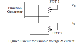
| On the development of relay software, it was necessary to validate the characteristic generated by software. In order to compute the values of resistance and inductance three variables are required i.e. system voltage (VR), current (IR) and phase angle between these two (θ). To test any distance relay, it is normal practice to keep any one of the input parameter either relay voltage or relay current constant and compute second parameter for different values of phase angle between them. Therefore all the three input parameters; VR, IR and θ are required for testing. Therefore for testing purpose hardware is required to provide variable voltage, variable current and variable phase shift between them. The Figure 5 shows the circuit diagram to get the variable voltage and variable current for the relay. Two potential dividers are connected across the function generator (POT 1 and POT 2; each 10 k). Hence the voltage and the current can be independently controlled under: |
 |
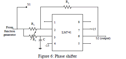
| The Figure 6 shows the circuit diagram of a phase shifter. The phase shift between input and output signals (S1 andS2)is given by; θ = 2 tan-1 (2πR3C) R1 = R2= 3.9 kΩ. |
| R3 = 100 kΩ (POT) |
| C =0.23 *10-6 farad, hence using variable resistance R3 (POT)the phase shift between voltage signal (S1)and current signal (S2)can be varied. |
 |
| With this arrangement all the three input parameters; VR, IR and θ are available with independent control. Trip Circuit:A circuit is required in order to process the trip signal generated by the software when trip condition is satisfied. This circuit is shown in figure 7 Circuit components:R = 3 kΩ, Transistor (npn): BC547, Miniature power relay: O/E/N , 58-12-2c, 0618, nominal voltage 12Volts |
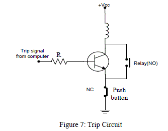 |
| .The trip circuit is designed in order to process the trip signal generated by the relay software. The software generates a trip signal of magnitude 5 Volts. This signal is applied to the base of the transistor which serves as switch in trip circuit. Whenever the trip signal is applied to the base of transistor, the relay coil gets energised and closes its contact. The circuit breaker will trip. Hence the output to the base of the transistor will get disconnected. This will result into resetting of the relay. In order to avoid this NO of the relay is connected across the transistor. This will hold the relay in ON condition even if the transistor resets. Push button (PB) is used to reset the relay. 1. Function generator to generate the test signal. 2. Digital Storage Oscilloscope (DSO) to see nature and the phase shift between two analog signals. 3. Regulated power supply (+/- 15volt for IC circuit). 4. Phase shift circuit (LM741). 5. Potential divider. 6. Trip circuit. 7. Automation module USB4711/A. 8. Computer. |
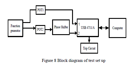 |
| For testing the relay software basically two variable sinusoidal signals (Voltage and Current) are required with the arrangement of generating phase shift (θ0) of 0 to 90 degree between them. The signals are represented as; |
| VR = lVRl∠00 and IR = lIRl ∠θ0. |
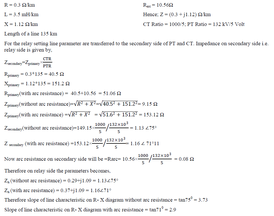
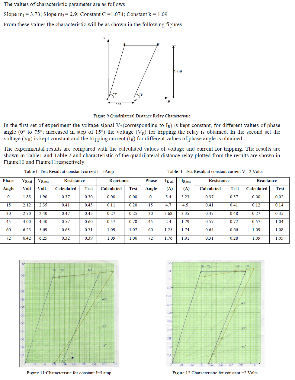
| A sinusoidal signal is taken from the function generator. It is given to two potential dividers so as to get variable voltage and current (a voltage proportional to the current). The current signal S2 then given to the phase shifter; hence at the output of the phase shifter lIRl ∠θ0 signal is obtained. These two analog signals are fed to USB4711/A. Signal VR is fed to analog input channel no. 1 of USB4711/A through variable resistance. Similarly second signal lIRl ∠θ0 is fed to the USB4711/A through analog input channel no.2. These two analog signals are fed to the computer through USB4711/A device. The software checks the conditions to generate quadrilateral distance relay characteristic and if the conditions are satisfied, trip signal is generated. Quadrilateral Distance Relay is used to protect high voltage transmission line. A transmission line with following parameters is assumed for the protection, |
 |
 |
VI. CONCLUSION |
| The objective of this paper was to design and develop the numerical quadrilateral distance relay. Mathematical analysis is carried out to generate the tripping characteristic for the quadrilateral distance relay. Software based on differential equation principle is developed to compute the resistance and reactance from the voltage and current samples of a four sample window. These values of resistance and reactance are used in the quadrilateral distance relay algorithms. For testing the relay hardware is designed to get the variable voltage and current and phase shift between them. A transistorised trip circuit is also designed to test the relay. The analog voltage and current signals are processed through USB4711/A device. The relay is tested as per the standard procedure for testing any distance relay. It is observed that the relay software is capable of distinguishing between fault and the healthy condition. The time response of software to issue trip signal is high. The developed software is capable of sampling the input analog signal with a maximum frequency of 700 samples/seconds. The generated distance relay characteristic is adaptive, with a provision to change the values of characteristic parameters. The test results are in close agreement with the mathematically computed values of voltage/current throughout the tripping region. Hence it is concluded that the designed numerical quadrilateral distance relay is working satisfactorily. |
References |
|