International Journal of Innovative Research in Science, Engineering and Technology
ISSN ONLINE(2319-8753)PRINT(2347-6710)
ISSN ONLINE(2319-8753)PRINT(2347-6710)
S.Sivanaga MalleswaraRaouthor1, Ch.V.S.ParameswaraRao2
|
| Related article at Pubmed, Scholar Google |
Visit for more related articles at International Journal of Innovative Research in Science, Engineering and Technology
The main objective of this work is to evaluate the best WEDM process parameters for machining 18-4-1 grade High Speed Steel (HSS) of different thickness ranging from 5mm to 80mm. The experiments are carried out on work pieces by varying the power input. The best power value at which the machining is stable with high cutting speed is identified. Width of the machined slot is measured and Spark gap is calculated for the machining at the corresponding power. The material removal rate (MRR) is computed. Surface roughness value is measured on the machined surface. The machining parameters at different power inputs are recorded. The experiments are repeated for all the job thicknesses under study. Mathematical correlations were developed using software for computing MRR and power input with respect to thickness of the job to be machined. The parameters evaluated and mathematical correlations are useful in setting the machine for the required machining criteria.
Keywords |
| HSS, MRR, Power, Thickness, Surface roughness |
INTRODUCTION |
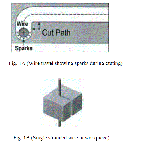
| Wire EDM machining (Electrical Discharge Machining) is an electro thermal production process in which a thin singlestrand metal wire in conjunction with de-ionized water (used to conduct electricity) allows the wire to cut through metal by the use of heat from electrical sparks. Due to the inherent properties of the process, wire EDM can easily machine complex parts and precision components out of hard conductive materials. Wire EDM machining works by creating an electrical discharge between the wire or electrode and the workpiece. As the spark jumps across the gap, material is removed from both the workpiece and the electrode. To stop the sparking process from shorting out, a nonconductive fluid or dielectric is also applied. The waste material is removed by the dielectric, and the process continues. In wire EDM machining, a thin single-strand metal wire, usually brass, is fed through the workpiece. Fig. 1A and fig. 1B shows the cutting process of a workpiece by a single stranded thin wire. The wire, which is constantly fed from a spool, is held between upper and lower guides. The guides move in the X-Y plane, and sometimes the upper guide can also move independently giving rise to transitioning shapes (circle on the bottom square at the top). This gives the Wire EDM the ability to be programmed to cut very intricate and delicate shapes. The wire-cut uses water as its dielectric with the water's resistivity and other electrical properties carefully controlled by filters and de-ionizer units. Pure water is an insulator, but tap water usually contains minerals that cause the water to be too conductive for WEDM, The deionized water cools and flushes away the small particles from the gap. |
 |
| HSS and its USES: The main use of high-speed steels continues to be in the manufacture of various cutting tools: drills, taps, milling cutters, tool bits, gear cutters, saw blades, etc., although usage for punches and dies is increasing. High speed steels also found a market in fine hand tools where their relatively good toughness at high hardness, coupled with high abrasion resistance, made them suitable for low speed applications requiring a durable keen (sharp) edge, such as files, chisels, hand plane blades, and high quality kitchen, pocket knives, and swords. The various grades of HSS we use are identified by M1, M2, M7 and M50, M1 being the most expensive grade. Very few woodworking tools are made from HSS. It is too expensive to use for large tools, very tough to machine and can be subject to breakage with rough treatment in hand held equipment. M1 is the hardest and also the most brittle of the bunch. We use M1, M2 and M7 for applications when better tool life is required and breakage is not a problem. M50 is used when breakage could be an issue. |
II. LITERATURE REVIEW |
| Subrahmanyam and Sarcar [1] optimized the machining parameters for the machining of H13 HOT DIE STEEL of 5mm thickness, with multiple responses Material Removal Rate (MRR), surface roughness (Ra) based on the Grey– Taguchi Method. Vishal Parashar et.al [2] performed experiments on Stainless Steel grade 304L of 10mm thickness under different cutting conditions of gap voltage, pulse ON time, pulse OFF time, wire feed and dielectric flushing pressure. The authors discussed the analysis of variance (ANOVA) technique was used to find out the variables affecting the MRR and Variation of the MRR with machining parameters was mathematically modelled by using the regression analysis method. Muthu Kumar et.al [3] Demonstrated the optimization of Wire Electrical Discharge Machining process parameters of Incoloy800 super alloy with multiple performance characteristics such as Material Removal Rate (MRR), surface roughness and Kerf based on the Grey–Taguchi Method. Gap Voltage, Pulse On-time, Pulse Off-time and Wire Feed are considered as process parameters and the relatively significant parameters were determined by Analysis of Variance. The variation of output responses with process parameters were mathematically modelled by using non-linear regression analysis method. Kanlayasiri and Boonmung [4&5] optimized the parameters effecting surface finish, for machining DC53 tool steel of 27mm thick with using 0.25mm diameter wire by designing the experiments with Taguchi method. The authors developed mathematical model for optimization to predict surface roughness values and errors. The developed model has shown a maximum error of 30%. Mohammadi et al. [6] performed 54 precision turning experiments. ANOVA is used for analysing the effect of input parameters on response. The authors considered the power, spark-on time, spark-off time, wire velocity, wire tension, wire speed and rotational speed as parameters and material removal rate as response. The authors developed mathematical relations for determining the material removal rate. Haddad and Tehrani [7] performed turning operations using L18 orthogonal array on DIN X210 Cr 12 steel. The authors derived mathematical model for material removal rate determination and its effect on surface roughness and roundness of machined surface. The die rotational speed, power and pulse off time exhibit significant effect on material removal rate. Tarng et al. [8] optimized the cutting parameters for better cutting performance using feed forward neural network through simulated annealing algorithm. The process parameters considered for optimization are thickness of work piece, material, spark-on time, spark-off time, machining current, voltage and capacitance on cutting speed and surface roughness as response. The authors machined SUS 304 stainless steel of 10 and 15mm thicknesses. The predicted optimized values are: For 10mm thick job: Ra value 16.1μm, cutting speed 1.63mm/min For 15mm thick job: Ra value 1.65μm, cutting speed 1.65mm/min |
| Jesudas et al. [9] developed a mathematical model using Taguchi analysis for optimizing the parameters of machining bronze-alumina alloy metal matrix composite. L9 orthogonal array is followed for design. ANOVA is applied to find the velocity of the optimal parameters derived. Lok and Lee [10] machined 10 samples of Sailon material, 40mm thick under pre-set conditions, evaluated MRR as 4.5-6.0 mm3/min. The authors compared the machining rate of Sailon with that of SKD11 steel and found that sailon’s machinability is poor. It was also revealed that the material removal rate increased with increase in machining current to some extent and then decreased. Kuriakose and Shunmugam [11] designed the experiments using Taguchi L18 array and conducted on Ti6A14V material with 0.25mm diameter brass coated wire under pre-set conditions, 80V, 8-12A machining current, 4-8μs pulse time. Formation of oxides was observed due to high temperature generation, macro and micro level stresses induced during the process. The authors observed that when the time between two pulses is larger, non-uniform cooling and heating occurs and suggested coated wire as electrode from metallurgical point of view. ` Kadam and Basu [12] performed experiments on 17.3mm thick HC-HCr steel with 0.25mm diameter wire by varying duty factor, machining current and wire speed. The authors optimized the cutting speed and surface roughness and developed mathematical equations using regression analysis. Rao et al. [13, 14] studied the effect of process parameters on the yield criteria for machining different nonferrous materials and developed mathematical correlations to evaluate the parameters. Siva and Rao [15] determined the effect of the input parameter i.e. thickness of the job on output parameters such as discharge current, cutting speed, spark gap/over cut, metal removal rate and surface roughness value of high carbon high chromium steel (HC-HCr), a die steel cut by wire-electrical discharge machining (WEDM). To obtain a precise workpiece with good quality, the parameters to be set on the machine are optimized experimentally. The output criteria can be estimated for a given thickness of the workpiece using the mathematical correlations developed. |
III. EXPERIMENTATION |
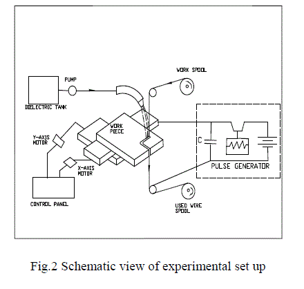
| Fig. 2shows the schematic view of the experimental set up. |
 |
 |
| Gap voltage : 80 volts |
| The HSS specimens of 20mm x 40mm size on thicknesses 5, 7.5, 10, 12.5, 15, 17.5,20,25, 30, 35, 40, 45, 50, 55, 60, 65, 70, 75 and 80mm are prepared. The experiments are conducted on the work piece of every thickness by cutting L shape and “[“shape by varying the machining current from a lower value to a value where the machining is in consistent in 5 steps. At every machining current, I value the machining criteria is measured. The machining current, I value at which the machining is consistent with continuous cutting, better finish with least wire rupture is selected as optimal. The cutting speed is noted from the machine display, surface finish is measured on “[“cut using Talysurf. The cutting width is measured on L cut with shadow graph and checked with microscope. The spark gap (wire off set) is calculated from cutting width. Cutting width, W= d+2 x Sg, where d is the wire diameter and Sg is the Spark gap. The MRR is calculated as, MRR = T x W x Cs where Cs is the cutting speed. The optimum values of machining current, cutting speed, spark gap and MRR for every thickness are used for plotting the curves and best fit curve is selected using the software. The mathematical relation is generated for this best fit curve and statistical analysis is performed to find the fitness of the curve. |
IV. RESULTS AND DISCUSSIONS |
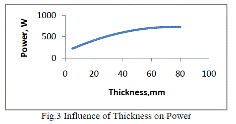
| Fig.3 explains the effect of thickness of work piece on Power input required for cutting. The plot envisages that the power requirement is increasing with increment in thickness. With increase in thickness, the material to be removed will be more which demands more energy. The energy will be supplied by increasing the machining current, in turn power. This may a reason for the increase in power. However the machine will have its own limitation of power input which is again a limitation of size of the work piece to be machined. The variation can be used to develop the mathematical correlation for determining the power required for machining the given HSS work piece. |
 |
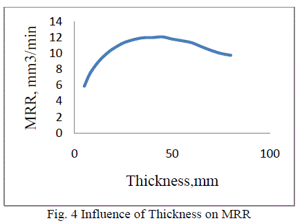
| Fig.4 depicts the influence of thickness on material removal rate (MRR). It is evident that the MRR is increasing up to 45mm thickness of job and then decreases. As the thickness of job increases, more amount of material is to be melted which requires high power. The power input may be a machine constraint. Moreover, at higher power levels the spark will jump longer causing wider cut at the cost of cutting speed. At the same time, the wire wear will be higher at higher power levels. Some power is lost in wire wear. This may be a reason for lower cutting speed and MRR at higher thick jobs. The plot is useful in developing the mathematical correlation for determining the MRR for machining the given job. |
 |
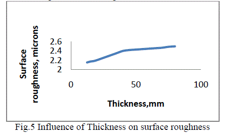
| The variation of surface roughness with increase in thickness is shown in Fig.5.The plot envisages that the roughness is increasing with increase in thickness. However the variation is only little and is between 2 to 2.5 microns Ra value. The discharge current or power requirement will be increasing with increase in thickness and causes long jump of high energy spark. The high energy sparks will jumps longer resulting in generation of rough surface. The same predictions are also evident from the fig.3 and fig.4. The plot is useful in predicting or estimating the surface roughness which can be achieved for a particular thick job. |
 |
| Mathematical correlations: The mathematical correlations are developed using Origin software for the best fit curves and statistical analysis is conducted to find the fitness of the correlations. The general form of correlation developed is as follows. The relation for Power is |
| P = 669.6+{838.4/ [1+ exp (T – 9.52)/ 18.36]} (1) |
| Where P = Power inwatts,T = thickness in mm. From the statistical analysis it is observed that the regression coefficient is 0.97 and standard deviation is 0.03. |
| MRR= 6.08- {4.66/ [1+exp (T-70.5)/3.53]} (2) |
| Where MRR= Material removal rate. |
| From the statistical analysis it is observed that the regression coefficient is 0.99 and standard deviation is 0.02 The statistical analysis is confirms the fitness and validation of the correlations. |
V. CONCLUSIONS |
| The influence of parameters, like power input, job thickness, on the machining criteria such as cutting power, cutting width, surface finish, material removal rate are determined. The results are useful in setting the parameters required for quality cuts on HSS. Suitable parameters can be selected for machining with the wire available. The mathematical relations developed are much more beneficial for machine settings, to estimate the cutting time, cost of machining and accuracy of cutting for any size of the job within machine range. The maximum error obtained in the calculated values and experimental values are less than 2%. These results will be useful to make the Wire EDM system to be efficiently utilized in the modern industrial applications like die and tool-manufacturing units for parametric setting, machining time and cost calculations and also for process planning. |
ACKNOWLEDGMENT |
| Authors’coveys their sincere thanks to Ratna Tool works, Hyderabad for extending cooperation in machining and measurements. |
References |
|