ISSN ONLINE(2319-8753)PRINT(2347-6710)
ISSN ONLINE(2319-8753)PRINT(2347-6710)
Ketul B. Brahmbhatt1, Dipal M. Patel2, Nirmit K. Sanchapara3
|
| Related article at Pubmed, Scholar Google |
Visit for more related articles at International Journal of Innovative Research in Science, Engineering and Technology
Couplings are most commonly used for connection and transmitting power and motion. Couplings are necessary to connect one shaft to another or to couple a drive shaft to drive shaft. For better working of coupling or any other mechanical component designing and manufacturing is very important term. In this paper design of coupling is considered an easy way; out of the traditional design process. In modern era, many modelling software is available in the commercial market. Three dimensional modelling can easily generate in these kind of software for better imagination, visualization and better understanding; as well as to prepare manufacturing drawings and flexible as compared to two dimensional traditional drafting. But 3D modelling process is a very time consuming and it required skill on these kind of software. By using Parametric modelling makes this creating task stress-free and take very less time because basic features and relations between them are in constant fashion for a specific product. In this paper interface of commercially available software like Pro-Engineering wildfire 5.0® and Microsoft office Excel® spreadsheet for 3D parametric modelling purpose. By parametric designing concept different products variants of the mechanical component have been executed in Pro/Engineer Wildfire.
Keywords |
| Coupling, Parametric Modelling, design, Excel spreadsheet. |
INTRODUCTION |
| The basic function of coupling is transmitting torque from one shaft to the other. There are two types of coupling (1) rigid coupling (2) Flexible coupling. Coupling which cannot accommodate misalignment are called as rigid coupling. These type of couplings are normally used when the load transmission is very low speed. Flexible coupling are characterised by their ability to absorb some amount of misalignment. This capability provided by having some flexible element in coupling. In this paper only flexible Oldham coupling is consider for parametric modelling. For generation of part model for coupling to generate part of flange following parameters are required like inner diameter, outer diameter, Slider height, slider width, hub height and thickness and flange thickness. All these parameter are change with change in application of coupling in practical use so this change can easily made by Microsoft office excel and pro-Engineering Wildfire 5.0 integration. This excel file easily save all coupling data in one file format. This kind of integration can be consider as automation in 3D modelling. In general parametric modelling in the field of Computer Aided Design means giving the relations between several dimensions of the universal part to its main nominal dimension. For example, in the case of Oldham’s coupling the nominal dimension is shaft dimension as the size of the whole flange is changed with the change in shaft dimension. The relationship between the otherdimensions to the effective dimension is called “Parent-Child” relationship. The Modelling relationship is explained here by the example of a simple pin design. A fig 1.of standard pin is shown above with the dimension notations. |
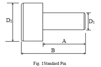 |
| The parent child relationship can be given by, |
| A = 1.5 * D1 , B = 0.8 * D1 and D2 = 2 * D1. |
| The user can specify a value for D1 and the corresponding size of the pin can be created using this parametric relationships. This feature is helpful to create several variations of given product with very little effort. |
II. LITERATURE REVIEWS |
| Many research efforts have been made in the area of parametric modeling. Zhang et al. [1] shows modeling automation system for electronic package thermal analysis using Excel spreadsheet. Trivedi et al. [2] described the technique of 3D parametric modeling for product variants using case study on inner ring of spherical roller bearing. They explored the method for integration of Pro/Engineer with Microsoft Excel. Chu et al. [4] developed computer aided parametric design for 3D tire mold production. Thakkar and Patel [3] defined the technique for interfacing through MS Excel and C language by the case study of pulley design. Shah Dhaval [5] described parametric modelling and drawing automation for flange coupling using excel spreadsheet. |
III. STEP FOR MODELLING AUTOMATION |
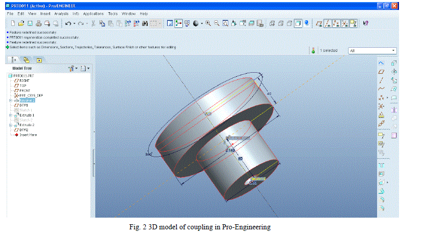
| Pro Engineering is a powerful and most commonly used modelling generation tool to validate parametric design of the component. Pro Engineering replicates all parameters and geometric data of the part in a simple text data format. This data can be modify by adding new feature, deleting existing feature, suppressing the feature and changing the dimension of the feature. A Graphics user interface (GUI) can directly modify the part model and can be compelled according to the user input in user interface. Here Microsoft Excel and Pro Engineering are combined by Excel Analysis tool which perform as an interfacing media. Excel spreadsheet can be transfer to pro Engineering data sheet by using Excel Analysis tool. Step-1 Generate a universal model A 3D model of the coupling with all features with dimensions and proper constraints have been generated as shown in the below figure 2. This model can be called as universal model and it is the model that has to vary with dimensions in excel data sheet. This file is than saved. |
 |
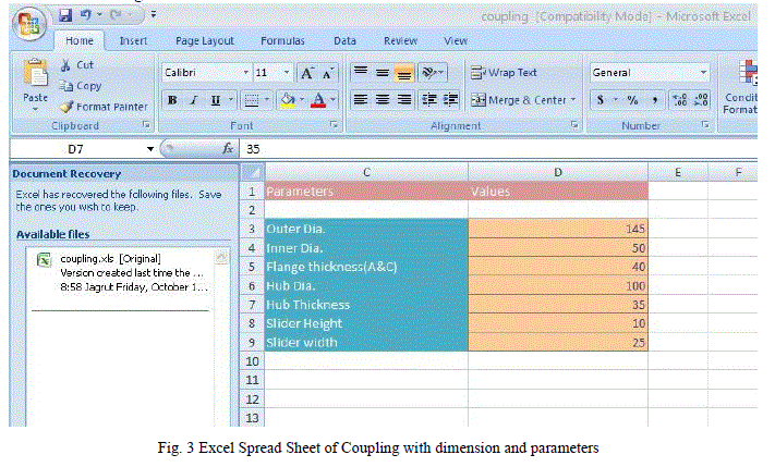
| Step-2 Generate an Excel spreadsheet An excel sheet with all parameters is generated as shown in above fig 3. This sheet contains all values of required dimensions. It is than saved to operating system. The relations between all dimensions to the shaft dimension are entered in such a way that they all get varied with the shaft diameter. This is done by using “Function” tool from Microsoft office excel. By applying cell addresses to the function demands equations between particular dimensions and shaft dimensions can be generated. |
 |
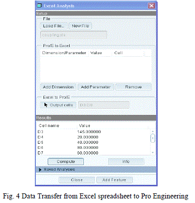
| Step-3 Data Transfer from Excel spreadsheet to Pro Engineering: An Excel Analysis Selection of external analysis feature by using analysis menu in Pro Engineering as shown in fig 4. below to transfer data from Excel spreadsheet to Pro Engineering. This is done by calculating dimensions from a nominal dimension by applying parent child relationship and then introducing all cell address to individual dimensions with a single file of pro-Engineers. |
 |
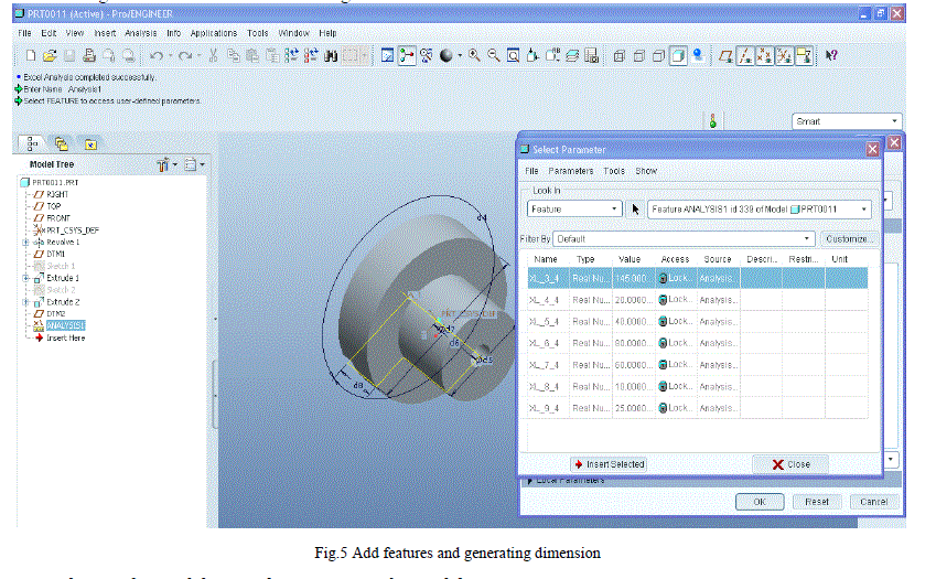
| Step-4 Adding features and generating dimension setup: Dimension setup is then saved by saving both excel and pro-E setup and relations are than given to dimensions for constraining them. It is shown in below fig 5. |
 |
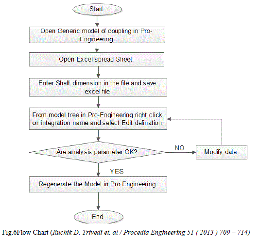
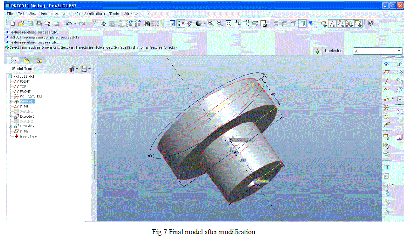
| Step-5 Technique for Modifying and regenerating the Model: The data in excel sheet is then changed according to convenience and saved. Here for our point of view as the nominal dimension is the shaft diameter so the diameter will be changed according to our requirement. Let us take our new shaft diameter as 65 than the new values will be calculated automatically for all other dimensions. The basic technique to modify the model as per coupling designation has been given in flow chart as shown in the fig 6. Then the rebirth process is done on the model for getting the required model of the flanges. The final model is received with new dimensions as shown in fig 7.below. |
 |
 |
IV. CONCLUSION |
| Above mention step of automation technique of creating model from Microsoft excel spread sheet is easier process and simple than any other interface. This process is very less time consuming than tradition model making method. But this process only valid for Oldham coupling. By using this method time required to modified the dimension of couplings less than in Pro-engineering in which open each part and modified each part individually. This method of parametric modelling interface with Microsoft excel just open excel sheet and enter new dimension and get changes in part model of Pro-Engineering. This interface is very useful for design and analysis. This automation can further be used for exporting this model to the Analysis package, CAM package and simulation purpose. |
References |
|