Keywords |
| Relay aided cellular networks, Decode and Forward relaying, Energy efficiency, Coverage capacity. |
INTRODUCTION |
| Relay aided transmissions provide significant coverage extension and energy gain in cellular networks. The cellular
principle partitions a geographical area into cells containing each, a base station and a number of mobile terminals.
The application of the relay concept to cellular networks, however, raises, many technical issues such as the best
position of relay station (RS) placement, coverage extension, energy consumption etc. Relays have been introduced in
the evolving cellular systems as a solution to improve the system coverage and increase the user capacity in cellular
region. Multiple types of relaying methodologies have been proposed to achieve these goals. The notion of Relay
Efficiency Area and a geometrical model for energy efficient relay placement, for both uplink and downlink
transmissions, which allows meaningful performance analysis without the need for excessive simulations. The urban
cell RS placement model is used to compare both the energy consumption and coverage capacity based on above
rooftop model (relay to base station link based on distance). |
| Recently relay networks have been widely considered as supplementary technology in next generation wireless systems
such as Fifth generation (5G), Third Generation Partnership project-Long Term Evolution (3GPP-LTE) and LTE-A is
envisioned as part of future heterogeneous networks, along with macrocell, picocell, and femtocells [1]. Relaying in
IEEE 802.16m is performed using a decode and forward paradigm. Both time division duplex (TDD) and frequency
division duplex (FDD) modes are analyzed [2]. Heterogeneous networks based on different access technologies and
challenges associated with the deployment of traditional macro base stations can be overcome by the utilization of base
stations with lower transmit power was studied [3]. Resource allocation and relaying strategies in cooperative systems
targeted to improving the cell capacity or spectral efficiency [4]. To compare the system capacity according to the
throughput oriented and signal strength oriented relay selection rules, with considering the effect of relay location [5].
The proper planning of RS placements, the capacity of IEEE802.16j networks can be greatly enhanced by RSs,
especially when hotspots are present [6]. To analyse different relaying strategies, amplify-forward, decode-forward and
compress-forward, and compare their spectral efficiency [7]. The impact of relay station placement on the network
performance in the IEEE 802.16j network was studied. Specifically, the throughput maximization relay station
placement problem is mathematically formulated and its complexity was analysed [8]. Cross-layer resource allocation can efficiently support diverse QoS requirements over wireless relay networks. Both AF and DF relays shows
significant superiorities over direct transmissions when the delay QoS constraints are stringent. [9]. The Mobile multi
hop relay networks (MMR) to analyse the scalability of a wireless network is usually limited by the system radio
bandwidth and channel interference. The radio resource management which target at addressing capacity enhancement
have been extensively reported , and most of the research efforts at maximizing resource utilization [10]. Relay station
(RS) provide less functionality compare than the BS can forward high data rates to remote areas of the cell while
lowering infrastructure cost [11]. The synergy between OFDMA and relaying techniques offers a promising
technology for providing high data rate to WSs everywhere, at anytime [12]. |
SYSTEM MODEL |
| This system presents the cell and path loss models. There are two path loss models depending on the relay being below
or above rooftop. This system model analyze the path loss model based on the relay to base station link (above rooftop
model). |
System model for relay placement analysis: |
 |
| Consider a 6-sector hexagonal cell. Rcov refers to the maximum radius in hexagonal cell, which includes the coverage
extension provided by the relay station. |
 |
| The base station is located at the center of the cell and each sector is provided with a relay station, located at a distance
Dr from the base station. The 16 users are placed in random manner in a given cell area. Consider the urban cell
model, and HB, HR and HU denotes the heights of the base station, the relay station and the user respectively and rs
refers to the distance from the user to relay . The multiple access strategy allows right-angled (orthogonality) between
users, such that only one user is served for a given time and frequency resource. To assume the relay operates in the
same frequency resource as the user it serves (in band relaying). |
Channel model for half-duplex relaying: |
| The channel model for half duplex relaying performed in time division. Half duplex relays have one transceiver, so the
relay transmits and receives on the same sub channel on two timeslots. In the first timeslot, the source sends the data to
the receiver and the relay overhears (assuming cooperative relaying) the data. In the second timeslot, the relay resends
the data after some processing to the receiver which then combines the received signals from the relay station as well as from the source through the direct link using some combination techniques, such as, Maximum Ratio Combining
(MRC). Here, a transmission of unitary length is carried out in two phase of equal duration. And denote the
transmitted code words X1 and X2 for the user at each phase respectively, and Xr for the relay. Yr and Y1 respectively
are the received signals at the relay and destination at the end of phase 1, Y2 is the received signal at the destination at
the end of phase 2. Thus, the half duplex relay channel is written as follows: |
 |
| where Zr, Z1 ,Z2 are independent additive white Gaussian Noises (AWGN) with equal variance N. This system
respectively denotes hd, hs and hr the channel from user to base station (direct link), from user to relay and from relay
to base station. Consider the following path loss models: 1)Vicinity relay: The relay station is located below rooftop,
implying that the user to relay link is generally strong but at the cost of a weaker relay to base station link 2) Base
station like relay: The relay station is located above the rooftop, like a base station, the hr(Base station to relay) link is
very strong. In the system model for urban cell topography considers only in above rooftop model (Base station like
relay) based on the BS-RS distance based link. |
RELAYING SCHEMES AND POWER ALLOCATIONS FOR ENERGY EFFICIENCY |
| This system presents the full decode and forward coding scheme for half duplex time division relaying. For
each coding scheme, the power allocation minimizes the energy consumption while maintaining a given user rate Ʀ.
The user and the relay have individual power constraints over the two transmission phases within the same bandwidth,
respectively denoted as PU(max) and PR(max).Relay aided uplink transmissions, two schemes are considered in full
decode forward relaying scheme.Full decode and forward scheme: In the relay aided scheme, the user sends its
message to the base station with rate 2Ʀ and power PU. Then, the relay decodes the message, re-encodes it rate 2Ʀ and
forwards it to the destination with power PR . Two main decoding techniques are generally considered. 1)Two hop
relaying: It is used in practical system, in which the base station only considers the signal received from the relay and
thus the relay is merely a repeater. 2)Repetition coded decode and forward: The base station uses Maximum Ratio
Combining (MRC) and combines the signals received from both the user and relay. The power allocation set(PU,PR)
satisfies the following constrains: |
 |
| The allocation set which minimizes the energy consumption is |
 |
 |
| In the urban cellular network relay aided transmission considering path loss only, combining the signals received
from both the user and relay station as done in repetition coded full decode and forward only brings little energy gain
compared to two hop relaying. The relay aided transmission is more energy efficient than the direct transmission is
an out of range. Subsequently, to consider two hop relaying and repetition coded decode and forward as two variants
of the same reference scheme, denoted as Full Decode-Forward (Full-DF). |
| Characterization of Efficient Relay Placement: The characterization of efficient relay placement define the relaying
efficiency, both in terms of energy consumption and coverage extension. This system introduce the notion of Relay
Efficiency Area (REA), and build our geometrical model based on the Relay for both uplink and downlink
transmissions. |
| Analytical model for Relay Efficiency Area: A relay aided cell is characterized by the probability for a user to be
served by the relay station and by the energy saved by using the relay. On the contrary, of the message is relayed,
leading to sufficient energy gain to compensate for the shorter transmission duration. With regard to downlink, this
relaying condition is relevant for the full decode and forward scheme, |hd|² ≤ |hr |2, which is always satisfied since the
relay to base station link is very strong. The area of a cell sector can be expressed as follows. |
 |
| Totally 16 users are placed in a cell. The center node is act as base station and the six green nodes. are relay
station. In this mobile nodes are placed in infeasible direct transmission to base station and it is placed in small
characteristic distance from base station. In this mobile nodes are placed in feasible relay aided transmission to relay
station. These characteristic distances, as defined above, allow the direct computation of the overall probability of
relaying a communication, given that the user is randomly located in the cell, as well as the average consumed energy
to successfully transmit data in the line of sight propagation mode. |
ANALYSIS OF RELAY EFFICIENCY AREA (REA) FOR DECODE-FORWARD SCHEMES |
| The analysis of REA compute the sixteen characteristic distance (user position) for full decode and forward in relay
aided transmission for both uplink and downlink transmission. These characteristic distances are derived from the
channel condition. The common condition for relaying is expressed as follows, |
 |
| where Ad and Kd are given by path loss model constants dependent on the global location of the transmitter and
receiver(rooftop model). Pi=PU(max) for uplink and Pi=PR(max) for downlink. Where RDTx refers to relay-aided
transmission. |
| Conditions for energy efficiency of full decode-forward (Full-DF): |
| First, this system model focus on energy efficiency and derive the conditions for which the energy consumption using
full decode-forward (denoted EDTx ) relaying scheme. The energy efficient condition can be seen as the dual of the
throughput oriented condition is expressed as follows, |
 |
 |
 |
| In this above equation rs represents distance from user to relay station. Dr represents distance from base station to relay
station. Kd are given by path loss model constants dependent on the global location of the transmitter and
receiver(rooftop model). Ks are given by path loss model constants dependent on the global location of the
transmitter. Kr are given by path loss model constants dependent on the global location of the relay station and r
represents distance from user to base station. Note that Eqn. (4) is symmetric in hs and hr , meaning that it is valid for
both uplink and downlink. The solution of Eqn. (4) for α = 0 is almost solution for α = 1. α refers that path loss
exponent. In above rooftop (relay to base station link) model to described the coverage capacity and energy
efficiency based on the base station to relay station distance variation. |
ESTIMATED PROBABILITY OF RELAYING AND AVERAGE ENERGY CONSUMPTION |
| The estimated probability of relaying for relay aided communication to assume that the user is randomly located in the
cell and that the location distribution is uniform. Such distribution allows us to derive a simple expression of the
probability of relaying. The probability of relaying, denoted PRTX is obtained by the ratio of relaying area vs. total area
and is expressed as follows for hexagonal cells, |
 |
| Conditions on φ and ϕ are defined based on geometrical principles of a cell sector angles in upper bound and lower bound depend on Dmin ≤ x or (x,y)€ C(0, RDTx). Dmin refers
to as minimum distance (200 meters ie., relay to base station link is strong) in above rooftop model. The user is
positioned is longer distance to base station. So the user to Base station strength is too weaker. Compute the relay
energy consumption in full decode and forward relay scheme as follows, |
 |
| Where Dr is the distance from relay to base station. Where Kr is the global location of the relay station in above
rooftop model. Where Asector and PRTx are as defined in Eqn. (4) and Eqn. (9) respectively. These expressions for the
user and relay consumptions conclude the analysis of Relay Efficiency Area. |
EXPERIMENTAL RESULTS |
| The performance obtained by relay aided transmissions, highlight the energy efficient relay configuration (placement).
In this below figure 3 shows base station (pink colour) is placed in centre position, black colour nodes denotes mobile
users and green colour denotes energy efficient relay station. In this geometrical model for energy efficient relay
placement provide better coverage to cell edge users based upon the above rooftop model (relay to base station strength
based on distance). |
 |
 |
 |
| Fig3: Relay placement model in urban cell topography |
| In the above figure 3 shows the geometrical model for energy efficient relay placement position in the urban cell. In
the relay placement model, six relays are placed in fixed position in a cell. The base station covers the all areas in a
cellular region with the help of relay station in lower power consumption. So the mobile user does not need high power
to transmit the data to destination and also the cell edge users are connect effectively to base station without packet
loss or avoid path loss in the (transmission range distance is larger between source to destination) longer distance. In
the below figure 4 shows the data transmission in the propagation environment |
 |
| Fig 4: Data transmission from source to destination. |
| The packet is forwarding from source to destination with the help of relay station as illustrated in figure 4.The
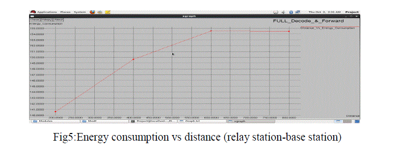
performance analysis based on the relay to base station distance is varied from 200m to 800m it covers 55% area in
minimum distance. (relay to base station distance) in the above rooftop model as illustrated in figure 5. To increase the
relay to base station distance from 200m to 800m at the time the link capacity between base station to relay station is
reduces. |
 |
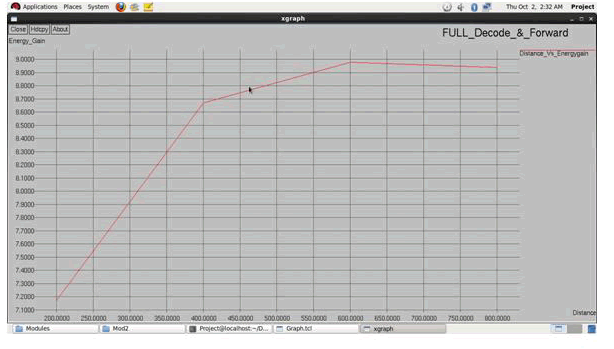 |
| Fig 6: Energy gain vs distance(relay to base station) |
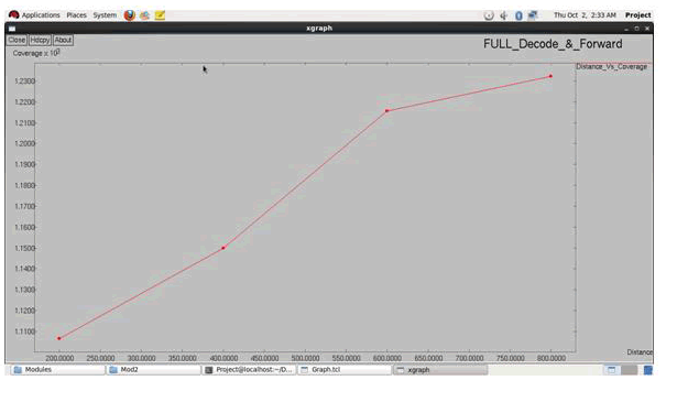 |
| Fig7: coverage vs distance(base station-relay station) using full decode and forward relaying |
| The performance analysis based on the link capacity in the relay aided transmission obtained the energy gain 35% in
the BS-RS link (minimum distance) is strong (link capacity strength is high). And it is obtained energy gain 11%
only in BS-RS link (maximum distance) is weak (link capacity strength is low) as illustrated in figure 6. In this
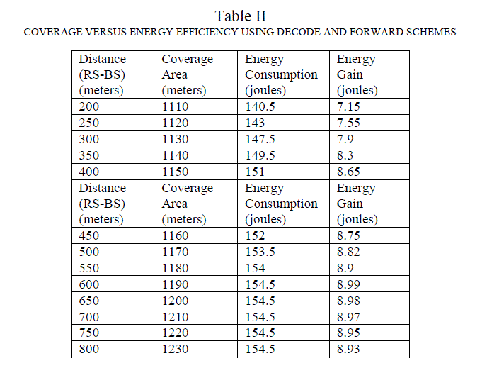
simulation result, figure 7 shows RS-BS distance based coverage. The RS-BS minimum distance covered 1110m. The
RS-BS maximum distance covered 1230m. To investigated relay placement for noise limited urban cells. The urban
cell coverage capacity and energy gain are analyzes based on the relay base station link (vary the distance between
relay to base station) using full decode and forward relaying scheme is shown in figure 5,6 and 7. |
CONCLUSION |
| Analyze the geometrical model for evaluating energy efficiency and coverage extension, and highlighted that a tradeoff
exists between them. Two options can be deduced from this work to efficiently deploy relays in a cell and use two
hop routing. In this case, attention has to be paid carefully positioning the relay station, so as to provide close to the
optimal coverage and energy gain. With regards to heterogeneous networks, the relay should be deployed in proper
position such that increasing the cell coverage has a minimal impact on energy efficiency. |
References |
- A. Ghosh, R. Ratasuk, B. Mondal, et al., “LTE-advanced: next generation wireless broadband technology [Invited Paper],” IEEE WirelessCommun., vol. 17, no. 3, pp. 10–22, 2010.
- K.Loa, C.-C.Wu, S.-T.Sheu et al., “IMT-advanced relay standards [WiMAX/LTE update],” IEEE Commun. Mag., vol. 48, no. 8, pp. 40–48, 2010.
- A.Damnjanovic, J. Montojo, Y. Wei, et al., “A survey on 3GPP heterogeneous networks,” IEEE Wireless Commun., vol. 18, no. 3, pp.10–21,2011.
- [4] B. Lin, P. Ho, L. Xie, and X. Shen, “Optimal relay station placement in IEEE 802.16 j networks,” in Proc. 2007 ACM Int. Conf. WirelessCommun. Mobile Comput. Proc., pp. 25–30.
- L.-C. Wang, W.-S. Su, J.-H.Huang, et al., “Optimal relay location in multi-hop cellular systems,” in Proc. 2008 IEEE Wireless Commun. andNetw. Conf., pp. 1306–1310.
- J. Huang, L. Wang, C. Chang, and W. Su, “Design of optimal relay location in two-hop cellular systems,” Wireless Netw., vol. 16, no. 8, pp.2179–2189, 2010.
- H.-C. Lu, W. Liao, and F. Lin, “Relay station placement strategy in IEEE 802.16j WiMAX networks,” IEEE Trans. Commun., vol. 59, no. 1,pp.151–158, Jan. 2011.
- K. Sambale and B. Walke, “Decode-and-forward relay placement for maximum cell spectral efficiency,” in Proc. 2012 European Wireless Conf.pp. 1-6.
- M.Alasti, B. Neekzad, J. Hui, and R. Vannithamby, “Quality of service in WiMAX and LTE networks,” IEEE Commun. Mag., vol. 48, no. 5, pp.104–111, May 2010.
- B. Lin, P.-H. Ho, L.-L. Xie, et al., “Optimal relay station placement in broadband wireless access networks,” IEEE Trans. Mobile Comput., vol.9, no. 2, pp. 259–269, Feb. 2010.
- G. Joshi and A. Karandikar, “Optimal relay placement for cellular coverage extension,” in Proc. 2011 National Conf. Commun., pp. 1–5.
- R. Youssef, M. Helard, M. Crussiere, and J. Helard, “Effect of relaying on coverage in realistic deployment scenarios,” in Proc. 2012International Conf. Telecommun., pp. 1–5.
|