Direct Torque Control is most widely used in industrial standard for high power induction motor drives. The conventional DTC method uses the hysteresis-based voltage switching method which has some drawbacks of higher torque ripple and speed pulsation. The main aim of the paper is to obtain the enhanced torque control and smooth flux trajectory. The proposed approach uses the sensorless drive which is incorporated in Direct Torque Control to improve the performance. Sensorless drive eliminates the shaft mounted speed encoder which is undesirable in a drive because it increases the cost and reliability problems. Sensorless method is used to estimate the speed signal with the help of machine terminal voltages and currents. The proposed method is simulated with the help of MATLAB and result shows that performances are improved.
Keywords |
| Direct Torque Control, MRAS, and
Induction motor. |
INTRODUCTION |
| In recent years the sensorless based direct torque
control of induction motor drive has grown significantly
due to its reduced hardware complexity, cost effective,
elimination of sensor cable, increased reliability and less
maintenance requirements [1], [2]. |
| The principle of conventional Direct Torque Control is to
controls the torque and flux directly or independently by
selecting proper inverter switching states [3] that includes
the hysteresis band controller which has some advantage of ease of implementation and simple structure.
Hysteresis controller has main drawbacks of higher
torque ripple, flux ripple and speed pulsation [4]. To
solve the above problems, a direct torque control with
space vector modulation schemes is introduced. In this
method, closed loop for estimation of torque and flux is
implemented as in DTC but the inverter switching states
is produced by SVM signal [5], [6]. |
| To obtain better torque and smooth flux control
of induction motor drives, various sensorless-based
methods have been used for speed estimation and give a
good performance in large speed range. The different
methods are speed adaptive flux observer [7], [8], model
reference adaptive system [9], [10] slip calculation
method and extended kalman filter [11], [12]. Among
various machine model-based methods, Model Reference
Adaptive System (MRAS) appeared to be the best
solutions for speed sensorless drives [13], [14]. |
| This paper proposes the Model reference adaptive system
which is used to estimate the rotor speed with the help of
machine terminal voltages and currents. MRAS observer
is widely preferred due to its ease of implementation with
high speed of adaptation for wide range of applications,
although this approach leads to small variations in low
speed region. The Popov’s hyper stability criterion is used
to estimate the stability of closed loop speed [5], [6]. The
proposed control scheme for sensorless based DTC-SVM
is elaborately discussed in this paper. |
| Section 1 describes the mathematical model of Induction
Motor drive. Section 2 describes the proposed sensorless drives and DTC-SVM. Section 4 shows the simulation
results for DTC, Sensorless DTC and Sensorless based
DTC-SVM. Section 5 gives conclusion and future works. |
SENSORLESS BASED DTC-SVM |
Machine Equations |
| The behavior of IM is analyzed with the use of space
phase quantities in a stationary reference frame. The
voltage balance equations for the d-q axes are as follows. |
 (1) (1) |
 (2) (2) |
 (3) (3) |
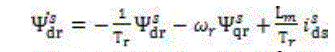
| The fluxes can be computed as |
 (4) (4) |
| The mechanical equation is given as |
 (6) (6) |
 (7) (7) |
| Where, |
| P- Number of poles |
 (8) (8) |
 (9) (9) |
 (10) (10) |
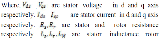 |
| inductance and mutual inductance. |
Proposed Model Reference Adaptive System |
| The proposed structure is a model-reference adaptive
system MRAS, it consists of three steps: reference model,
adaptive model and an adaptive method. The proposed
sensorless drive is presented in Figure 1. |
 |
| Both models are referred to in the stationary reference
frame. The output of a reference model is compared with
the output of an adjustable or adaptive model until the
errors between the two models vanish to zero. |
| Reference Model: This model receives the machine
stator side voltage and current signals and calculates the
rotor flux vector signals. The stator and rotor flux
linkages in the stator reference frame are defined as |
 (11) (11) |
 (12) (12) |
 |
 (13),(14) (13),(14) |
| Adaptive Model: The adjustable or adaptive model
equation is simpler and is obtained from the current model of
the machine equations in stationary reference frame using
stator currents if the speed signal is known. |
 (15) (15) |
 (16) (16) |
 |
| With the correct speed signal, fluxes calculated from
reference model matches with the adaptive model. |
| Adaptation Algorithm: An adaptation algorithm with
P-I control can be used to tune the speed when the error =
0.In designing the adaptation algorithm, it is important to
take account of overall stability of the system. Using
Popov’s criteria for hyper stability [18] for asymptotically stable system, the speed estimation equation is |
 (17) (17) |
 (18) (18) |
| Estimation accuracy is good if parameter variation is
considered as constant. |
Direct Torque Control with SVM |
| In Direct torque control, it is possible to control directly
the stator flux and the torque by selecting the appropriate
inverter state. To overcome the classical DTC drawbacks
like increased torque ripple, SVM based DTC is used
here. The block diagram of sensorless based DTC with
SVM is shown in fig 2. |
 |
| The proposed topology of the DTC-SVM comprises two
PI regulators for flux and torque. The controller receives
inputs in the form of torque and stator flux errors and
generates the inverter’s command signals. The SVM unit
produces the inverter control signals. It receives the
reference voltage in stator reference frame.SVPWM is a
digital modulation technique which treats sinusoidal
voltage as a constant vector rotating at constant
frequency. This PWM technique approximates the
reference voltage VREF by combination of the eight
switching patterns (V0 to V7). Figure shows space vector
representation. |
 |
| Steps involved in implementing the space vector PWM is
given as |
| • Calculation of , VREF and angle(α) . |
| • Calculation of T1, T2, T0. |
| • Calculation of switching time for each switch. |
SIMULATION RESULTS |
| To validate the effectiveness of the MRAS based DTCSVM
methods, a two-level sensor less based DTC-SVM
motor drive was developed in MATLAB environment
and simulation results are presented here in fig 6. The
Model Reference Adaptive System based DTC drive is
illustrated in Fig. 1. |
 |
| Fig.6 : MATLAB modelling of sensorless based DTC of Induction
Motor. |
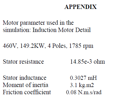
| Sensorless MRAS technique is employed for closed loop
speed estimation. A simulation work has been carried out
on an induction motor with the specifications given in
appendix. The proposed MRAS scheme is simulated in
MATLAB/SIMULINK which is shown in Fig.7. Fig. 8
and Fig. 9 shows stator current for DTC of induction
motor and sensorless based DTC of induction motor. |
 |
| Fig.7 : Implementation of MRAS scheme in IM. |
| When load torque of 500Nm is applied at time t = 0.3s in
classical DTC and sensorless based DTC, same
magnitude of stator current is flow in induction motor.
But current pulsation in sensorless based DTC is
comparatively reduced. |
 |
| Fig.8 Stator Current for DTC of Induction Motor. |
 |
| Fig.9 Stator Current for Sensorless based DTC of Induction Motor. |
| Stator flux of direct torque control and sensorless based
direct torque control of induction motor is shown in Fig.
10 and Fig. 11.When compared with DTC, stator flux is
more uniform in sensorless based DTC. |
 |
| Fig.10 Stator flux trajectory for DTC of induction motor |
 |
| Fig.11 Stator flux trajectory for sensorless based DTC of Induction
motor. |
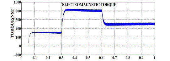
| Electromagnetic torque response for DTC and sensorless
based DTC for induction motor is shown in fig.12 and
fig. 14.The Fig. 12 shows the electromagnetic torque for
DTC of induction motor. Initially the motor run with a
electromagnetic torque of 300 Nm. At t = 0.3 s, the load
torque of 500 Nm is applied to the motor shaft while the motor speed is still ramping to its final value. This forces
the electromagnetic torque to increase to the maximum
value and then to stabilize around 500 Nm once the speed
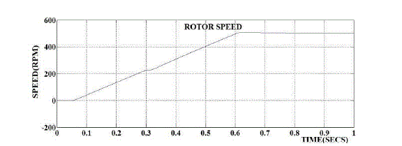
ramping is completed. Speed ramping is completed at t =
0.6s. |
 |
| Fig.12 Electromagnetic Torque for DTC of Induction Motor |
 |
| Fig.13 Rotor Speed for DTC of Induction Motor. |
 |
| Fig.14 Electromagnetic torque for sensorless based DTC of induction
motor. |
 |
| Fig.15 Rotor Speed for sensorless based DTC of Induction Motor. |
| In sensorless based direct torque control when motor is
starts with zero load torque at t=0s, it will oscillates and
settles to its steady state with 300Nm initially. When load
torque of 500 Nm is applied at 0.3 seconds applied, motor
oscillates and then settles at steady state. In steady state
the load torque oscillates between maximum and
minimum value of 520 Nm to 460 Nm. |
 |
| Comparison of torque ripple in DTC and DTC with
sensorless is shown in table. Therefore from results in
table it is inferred that proposed scheme has less torque
ripple, smooth flux response and less current pulsation. |
CONCLUSION AND FUTURE WORK |
| In this paper, sensorless based direct torque control
technology for induction machine has been proposed.
Speed estimation is achieved using model reference
adaptive system which eliminates the need speed sensor.
Sensorless based DTC improve induction motor
performance in terms of flux, torque and current
response. Application of Neuro-Fuzzy in error
minimization in MRAS will gives more accurate speed
estimation which will be future scope. The simulation
results verify that the proposed scheme improves the
performance of induction motor. |
 |
References |
- Domenico Casadei, Giovanni Serra, Angelo Tani, Luca Zarri, and Francesco Profumo,” Performance Analysis of a Speed-Sensorless Induction Motor Drive Based on a Constant-Switching-Frequency DTC Scheme IEEE Transactions On Industry Applications, VOL.39, NO. 2,pp. 476-484, March/April 2003.
- Haithem Abu-Rub, Jaroslaw Guzinski, Zbigniew Krzeminski, and Hamid A. Toliyat, “Speed Observer System for Advanced Sensorless Control of Induction Motor IEEE Transactions on Energy Conversion, VOL. 18, NO. 2,pp.219-224june 2003.
- I. Takahashi and T. Noguchi, ―A new quick-response and high efficiency control strategy of an induction motor, IEEE Trans.Ind. Applicat., vol.IA-22, pp. 820–827, Sept./Oct. 1986.
- D. Casadei, G. Grandi, G. Serra, and A. Tani, ―Effects of flux and torque hysteresis band amplitude in direct torque control ofinduction machines, in Proc. IECON’94, Bologna, Italy, Sept. 5–9, 1994, pp.299–304.
- D. Casadei, G. Sera, and A. Tani, ―Stator flux vector control for high performance induction motor drives using space vector modulation, in Proc. OPTIM’96, 1996, pp. 1413– 1422.
- P. Thoegersen and J. K. Pedersen, ―Stator flux oriented asynchronous vector modulation for AC-drives,‖ in Proc. IEEEPESC’90, 1990, pp. 641–648.
- A. Paladugu, B. H. Chowdhury, ―Sensorless control of inverter-fed induction motor drives‖, Electric Power Systems Research 77 (2007)619-629.
- M.Juili, K.Jarray, Y.Koubaa, M.Boussak, ―Lenberger state observer for speed sensorless ISFOC induction motor drives‖, Electric Power SystemsResearch 89 (2012) 139-147.
- T. Ravi kumar, Ch. Shankar Rao, Ravi Shankar ―Model Reference Adaptive Technique For Sensorless Speed Control Of Induction Motor, International Journal Of Engineering And Computer ScienceISSN:2319-7242 Volume 2 Issue 5 May, 2013 Page No. 1578-1583.
- M.K. Metwally ―Sensorless speed control of 4-switch three phase inverter fed induction motor drives at very low and zero speed‖Alexandria Engineering Journal (2013).
- Salomón Chávez Velázquez, Rubén Alejos alomares, Alfredo Nava Segura ―Speed Estimation for an Induction Motor Using the Extended Kalman Filter‖, Proceedings of the 14th International Conference on Electronics,Communications and Computers(CONIELECOMP’04) 0-7695-2074-X/04 $ 20.00 © 2004 IEEE.
- Americo Vicente Leite, Rui Esteves Araujo, and Diamantino Freitas ―A New Approach for Speed Estimation inInduction Motor Drives Based on a Reduced-Order Extended KalmanFilter‖ 0-7803-8304-4/04/$20.00 C02004.
- D. P. Marcetic, S. N. Vukasavic, ― Speed-Sensorless AC Drive With the Rotor Time Constant Parameter Update‖,IEEE Trans onindustrial electronics, VOL. 54,NO. 5,October 2007.
- P. Jansen, R. Lorenz, and D. Novotny, ―Observer-based direct field orientation: analysis and comparison of alternative methods,‖ IndustryApplications, IEEE Transactions on, vol. 30, no. 4, pp. 945–953, 1994.
- Y.D.Landau, Adaptive control- The Model Referencing Apprach,Marcel Dekker, 1979.
|