The motivation of this project is to produce three phase voltage with variable frequency and amplitude. This is achieved with the help of matrix converter, which is single stage AC/AC converter. It has more characteristics like sinusoidal input and output currents, voltage, unity displacement factor and limited frequency changer. The various modulation algorithms are used to control matrix converter. Most ideology behind the modulation algorithm is to get output voltages from input desired frequency and amplitude. The modulation algorithm can be applied to both direct and indirect matrix converter. The induction motor fed by three phase direct matrix converter which makes directly AC-AC power conversion is modelled using Space Vector Modulation technique for direct matrix converter in Matlab& Simulink. In this method, gate drive signals for the nine bidirectional switches are calculated to generate variable frequency and amplitude of sinusoidal output voltage from fixed frequency and amplitude of input voltage. This model provides the output upto 86.6% of input voltage and unity power factor. And also it reduces the effective switching frequency in each cycle and reducing the switching loses.
Keywords |
| Matrix converter, Space Vector
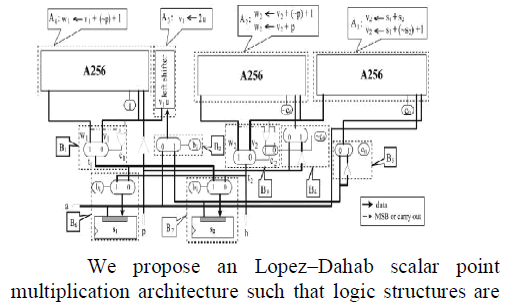
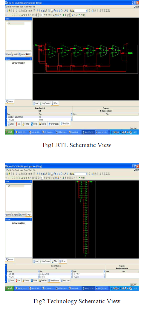
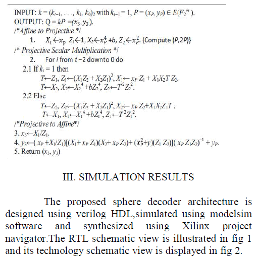
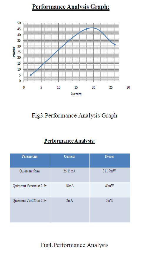
Modulation. |
INTRODUCTION |
| Three phase matrix converter is an AC-AC power
converter with nine bidirectional switches. Which are
arranged as 3 × 3 matrix and with any output phase can
be connected to any input phase. Some of the advantages
over this converter are providing bidirectional power
flow, absence of DC link capacitor, sinusoidal input and
output current with adjustable displacement angle. |
| Various modulation strategy for matrix converter has
been investigated due to harmonic spectrum, total
harmonic distortion (THD), complexity of implementation
and switching play an important roles. A complete mathematical analysis of the power circuit along with duty
cyle calculation is proposed for both low voltage transfer
ratio and high voltage transfer ratio. The basic matrix
converter is shown in below fig.1. |
 |
| Analysis and mathematical modeling of space vector
modulated direct controlled matrix converter IEEE (2010)
presented a paper about mathematical model for a space
vector modulated (SVM) direct controlled matrix
converter. Modelling stability analysis and control of a
direct AC/AC matrix converter based systems
MelakuMihretIEEE (2011) presented about direct and
indirect space vector modulation using matrix converter
switching configuration .To design a input filter to
maintain a harmonics balance technique. |
| An effective direct SVM method for matrix converter
operating with low voltage transfer ratio, Hong Hee lee
IEEE (2012) deals with the Common mode voltage using
the direct space vector modulation for power factor
compensation. Analysis and mathematical modeling for
Space Vector modulated direct controlled matrix converter
RuzlainiGhoni IEEE(2013) presented a paper about
mathematical model for a space vector modulated (SVM) direct controlled matrix converter. The duty cycles of the
switches are modeled using space vector modulation for
voltage transfer ratios about 0.5 to 0.866.The matrix
converter simulations are loaded by passive RL load and
active induction motor are performed. |
| In this paper design a matrix converter which is a ACAC
power converter which is composed of an array of
mxn bidirectionalsemiconductor switches, connecting
each phase of the input to each phase of the output using
venturini and space vector method which provides
sinusoidal input and output waveforms, with minimal
higher order harmonics and no sub harmonics. The output
is tested for different load condition. |
SPACE VECTOR MODULATION |
| The space vector algorithm is based on the
representation of the three phase input current and three
phase output line voltages on the space vector plane.
Space Vector modulation is a special switching sequence
which is based on upper switches of a three phase direct
matrix converter. SVM which treats a sinusoidal voltage
as a phasor or amplitude and it rotates at a constant
frequency ��. The amplitude vector which is represented
as d-q plane and it denotes the real and imaginary axes. |
 |
| For any combination output voltage and input current
sectors, the four combinations can be identified, which
reduce output voltage and input current vectors. Four
switching patterns are analyzed and simulated for direct
space vector modulation they are asymmetrical single
sided, which uses only one of the three zero vectors. |
| The switching combinations can be classified into three
groups they are synchronously rotating vectors, stationary
vectors and zero vectors. Matrix converter connects load
directly to the voltage source by using nine bidirectional
switches, the input phases should not be short circuited
due to inductive nature of the load, the output phases
should not be kept open. If the switching function of a
switch, ������ in equation (1) |
 (1) (1) |
| For a balanced three phase sinusoidal system the
instaneous voltage may be expressed in equation (1) |
 (2) (2) |
CONTROL ALGORITHM |
| The transfer function approach is applied for both
Voltage Source Inverter (VSI) and Voltage Source
Rectifier (VSR). |
Space vector modulation for rectifier stage |
| The rectifier part of equivalent circuit for Current
Source Rectifier (CSR) with averaged value of IDCmay be
expressed in equation (2) |
 (3) (3) |
 |
 |
 (5) (5) |
 (6) (6) |
 |
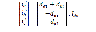
| The Rectifier Input Current vector diagram is shown in
Fig 3.The nine Rectifier switches have nine permitted
combination to avoid an open circuit in DC link. |
 |
 (7) (7) |
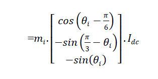
| The switching cycle within the first vector is
givenequation (7). |
Space vector modulation for inverter stage |
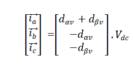
| The inverter can be assumed as a separate VSI. The
switching method is exactly similar to conventional VSI,
but owing to its virtual DC link,������ should be defined in
following equation (8) and the output voltage vector is
represented in fig 4 |
 (8) (8) |
| ������ is a peak value of input voltage and ������ is a input
displacement angle. The VSI switches can assume only
six allowed combinations which yield nonzero output
voltages. The inverter switches have eight permitted
combinations to avoid a short circuit. These combinations
include three zero and six non zero input currents. |
 (9) (9) |
 (10) (10) |
 (11) (11) |
 |
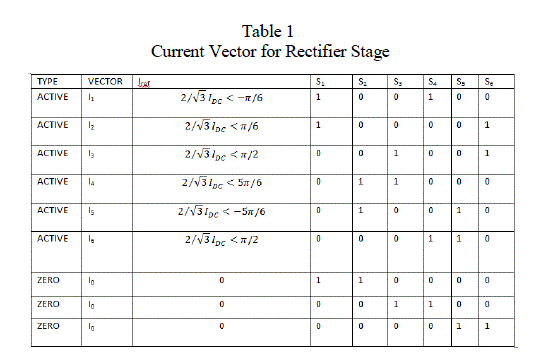
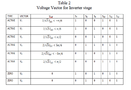
| The modulation algorithm is derived similar to VSR
and VSI expect in the opposite direction .since, both the
VSR and VSI hexagons contain six sextants, there are 36
combinations or operating modes. The Table 1 and Table
2 which describes the current and voltage vector. |
 |
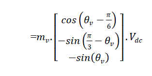 (12) (12) |
| The duty cycle of VSI are calculated in equation (13).
27 valid switch combinations giving the 27 voltage
vectors. |
 |
 |
SIMULINKMODEL |
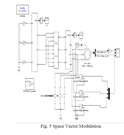
| The complete space vector modulation is shown in fig
5. It comprises of Input modulator, Output modulator,
Matrix converter modulator and Matrix converter IGBT
switches. |
 |
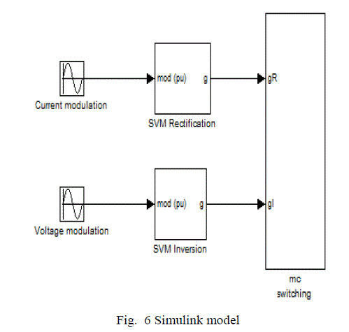 |
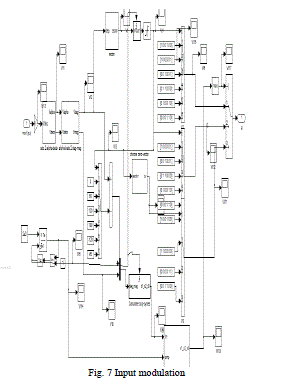
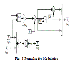
| The Fig 6 which shows the simulation model.
Simulation model which consist of current modulation
and voltage modulation which is shown in Fig 7 and
8through which it is connected to SVM rectification and
Inversion model. |
 |
 |
SIMULATION RESULT |
| The performance of the direct space vector modulation
method is applied to an AC/AC matrix converter. Through
matrix converter voltage source is connected to the
resistive load. The main circuit is to ideal, and the results
are calculated under the conditions of input power supply
and output load. |
 |
 |
 |
 |
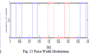 |
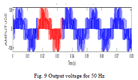
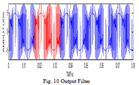
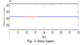
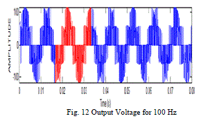
| Furthermore Fig 9 illustrates the Output voltage for 50
Hz, Fig 10 illustrates the Output Filter, Fig 11 illustrates
the Rotor speed, Fig 12 illustrates the Output voltage for
100 Hz, and Fig 13 illustrates the Pulse Width Modulation.
Through low pass filter higher order harmonics are
removed. |
 |
| The Simulation result carried out using
MATLAB/SIMULINK. It was loaded by three phase
induction motor with 3hp, 200V, 60Hz star connected.
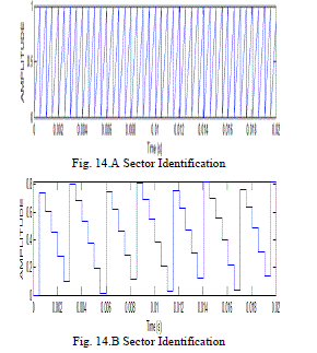
Fig.14 A&B represents the sector identification and
reference angle generation. The angle is generated from the reference output frequency by integrating.
The input and output line voltage with loaded passive
load. |
CONCLUSION |
| The simulink model of direct matrix converter for
control strategies like SVM technique has been
developed and its result are analysed. The significant
target to achieving frequency and amplitude has been
attaining from input by duty cycle calculation and
sequential piecewise sampling. As discussed earlier
the direct matrix converter has no efficiency than
indirect matrix converter. This constraint has been
overcome by the mathematical model that resembles
the operation of power conversion stage of matrix
converter. This makes the upcoming research on
matrix converter is easy and prosperous. |
References |
- M. Venturini, “A New Sine Wave in Sine Wave out, Conversion Technique Which Eliminates Reactive Elements,” in Proceedingsof Powercon 7, pp. E3/1-E3/15, 1980.
- M. Venturini and A. Alesina, “The Generalized Transformer a New Bidirectional Sinusoidal Waveform Frequency Converter with Continuously Adjustable Input Power Factor,” IEEEPESC’80, pp.242-252,1985.
- H.W. van der Broeck, H. Ch. Skudelny, and G. V. Stanke, “Analysis and realization of a pulse widthmodulator based on voltage space vectors,” IEEE Transactions on IndustryApplications, vol.24, no. 1, pp. 142–150, 1988
- L. Huber and D. Borojevic, “Space vector modulated three phase to three-phase matrix converter with input power factor correction,” IEEE Transactions on Industry Applications, vol.31,no. 6, pp. 1234–1246, 1995.
- D. Casadei, G. Serra, A. Tani, and L. Zarri, “Matrix converter modulation strategies: a new general approach based on space vector representation of the switch state,” IEEE Transactions on Industrial Electronics, vol. 49, no. 2, pp. 370–381, 2002.
- M. Jussila and H. Tuusa, “Comparison of direct and indirect matrix converters in induction motor drive,” in Proceedings of the 32nd Annual Conference on IEEE Industrial Electronics(IECON’06), pp. 1621–1626, Paris, France, November 2006.
- H. Karaca and R. Akkaya, “Modelling and Simulation of Matrix Converter under Distorted Input Voltage Conditions,” IEEE,2010.
- P. W. Wheeler, J. Rodriguez, J. C. Clare, et al.“Matrix Converters: A Technology Review,” IEEE Transaction onIndustrial Electronics, vol. 49, no.2, pp.276-288,2010.
- Odaka A, S.I., Ohgushi H, Tamai Y, Mine H, Ito J, “A Pam Control Method forMatrix Converter”. In Proc 200 JapanIndustry Applications SocietyConference,2005.
- [10] EbubekirErdem, Yetkin Tatar, and SedatSünter, “Modelling andsimulation of matrix converter using space vector algorithm”IEEE,2005.
- RuzlainiGhoni, Ahmed.N, “Analysis and mathematical modeling of space vector modulated direct controlled matrixconverter”, Journal of theoretical and applied informationtechnology, 2005.
- HulusiKaraca and RamazanAkkaya, “Modelling, simulation andanalysis of matrix converter using Matlab and simulink”.International Journal of Modeling and Optimization, Vol. 2, No.3. 2012
- Amin Shabanpour, SasanGholamian Ali Reza seifi, “Comparativestudies of different switching patterns for Direct and IndirectSpace VectorModulatedMatrix Converter”, Advances in PowerElectronics, 2012
|