ISSN ONLINE(2319-8753)PRINT(2347-6710)
ISSN ONLINE(2319-8753)PRINT(2347-6710)
Vivek Brahmbhatt1, Gaurav Patel2
|
| Related article at Pubmed, Scholar Google |
Visit for more related articles at International Journal of Innovative Research in Science, Engineering and Technology
Impeller blades are one of important element of a centrifugal fan.They are mostly categorised into six types: AF, BI, BC, FC, RT, RB among which the BI i.e. impeller with back blades are considered as highly effective. The succeeding paper presents the design methodology for the centrifugal fan system with impellers having backward blades. The numerical design technique is established for it and the CFD optimization has been carried out for volute casing to advance the outcomes which have been achieved from the numerical method. The outcomes are correlated with those obtained from the numerical method established. The concept of 2D steady state analysis is applied in the CFD analysis of the centrifugal fan. The volute casing was optimized by reducing the volute clearances by 10-15%. Hence the design procedure which includes the support of CFD analysis has been established effectively.
Keywords |
| Centrifugal fan, Radial Impeller, Backward Impeller, CFD, Fan Performance. |
INTRODUCTION |
| The centrifugal fan uses the centrifugal power generated from the rotation of impellers to increase the pressure of air when the impeller rotates. The gas near the impeller is thrown-off from the impellers due to the centrifugal force and then moves into the fan casing. As a result the gas pressure in the fan casing is increased. The gas is then guided to the exit via outlet duct. After the gas is thrown-off, the gas pressure in the middle region of the impeller decreases. |
| Centrifugal Fan consists of mainly two parts, namely, the volute casing and the impeller. Other parts are inlet duct, outlet duct, driving shaft and dive mechanism. As per reference of Bureau of energy efficiency India, the finding of performance assessment trials will automatically indicate potential areas for improvement, which could be one or more following: |
| Impeller Design |
| • Fan inlet |
| • Fan outlet |
| • Duct sizing |
| • Damper system |
| Change of impeller by a high efficiency impeller along with cone. |
| Change of assembly as whole by a higher efficiency fan. |
| Option raw edged efficient flat belts, or cogged raw edged v belt in place of conventional v belt systems, for reducing transmission losses. |
| `Adopting inlet guide vanes in place of discharge damper control. |
| Minimizing system resistance and pressure drops by improvement in duct system. |
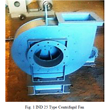
| Atre Pranav C. et al [1] developed the numerical procedure for the high efficiency fan impellers having airfoil blades and the volute casing for it. The air-foil blades were considered to have backward inclined orientation. R R Singh et al [2] determined Taguchi orthogonal array (OA) based design of experiments (DoE) technique with the required experimental trials. A. T. Oyelami et al [3] proved that the performance efficiency of all centrifugal blowers that utilize radial-flow impellers depends greatly onthe mode of impelling. N. Yagnesh Sharma et al [4] has shown that the performance of centrifugal fan could be enhanced by judiciously introducing splitter vanes so as to improve the diffusion process. Xiaomin Liu et al. [5] did the analysis centrifugal impeller firstly by solving the Navier-strokes with the spalart allmaras turbulence model and the performance curves were obtained. O. P. Singh et al. [6] discussed about the effect of geometric parameters of a centrifugal fan with backward- and forward-curved blades. S. Ziaei Rad et al [7] concerned with the finite element analysis andmodel testing of an industrial radial flow impeller. Liangwei Zhong et al [8] conversed the technique of three dimensional solid element model and assembly was used to determine the temperature field of radial-flow impeller. K. Vasudeva Karanth et al. [9] studied about the Effect of Radial Gap on impeller-diffuser flow of a centrifugal Fan. The work in this paper is divided in three stages. 1) Numerical Design 2) CFD Analysis and 3) Validation of simulated results with experimental results. |
 |
| Paper is organized as follows. Section II describes a brief of numerical design of centrifugal fan as per the different parameters. After the numerical design, CFD analysis is follows in section III, in which 2D modelling, meshing and distributions of pressure & velocity in flow domain is discussed. Section IV presents validation of simulated results with experimental results. Finally, Section V presents conclusion. |
NUMERICAL DESIGN |
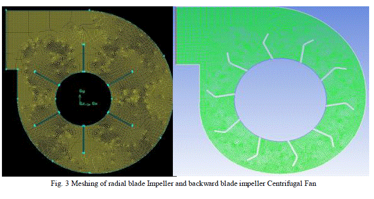
| The numerical procedure has been developed for the high efficiency fan impellers having backward blades and the volute casing for it. The design procedure gives the output parameters as below for the five functional input parameter requirements volume flow rate, Static pressure, speed of the fan rotation, mechanical efficiency and the motor BHP. |
 |
| The volute casing was designed according to four point method. From the previous case studies, it was decided to decrease the volute clearances by 10-14% for improving the results further. |
 |
CFD ANALYSIS |
| CFD analysis of the flow-domains of the casing is carried out in following manner: |
| A. 2 D Modelling |
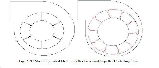
| For CFD analysis, inner cross-section of the conceptual models were created using Auto cad 2011 as shown below. |
 |
| B. Meshing flow domains |
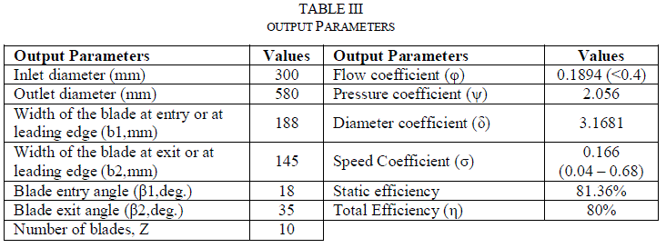
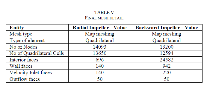
| In order to analyse fluid flows, flow domains are split into smaller sub domains which are made up of geometric primitives like quadrilaterals and triangles in 2D. The sub domains are often called elements or cells, and the collection of all elements or cells is called a mesh or grid. The process of obtaining an appropriate mesh (or grid) is termed mesh generation (or grid generation), and has long been considered a bottleneck in the analysis process due to the lack of a fully automatic mesh generation procedure. Specialized software programs like Gambit, Hyper-mesh have been developed for the purpose of mesh and grid generation, and access to a good software package and expertise in using this software are vital to the success of a modelling effort. Herein, the meshing software GAMBIT 2.3.16 is used for the meshing of all designs. |
 |
| C. Computational approach: |
| Fluent software is used for solving the Navier-Stokes equations governing the physics of the flow inside the centrifugal fan system. Fluent code is based on finite volume method. The Fluent is been used for pre-processing, solving and post-processing purpose. Run is fired on workstation having processor of 2GHz, 12GB RAM and three processors for parallel solving. Once the solution got converged, the results were post-processed. The velocity vectorsand pressure contours are plotted as shown in forthcoming figures. |
| D. Analysis Setup |
| Using Fluent software, the CFD analysis of the flow domains was performed for the specifications given in the following table: |
 |
| E. Velocity Distributions |
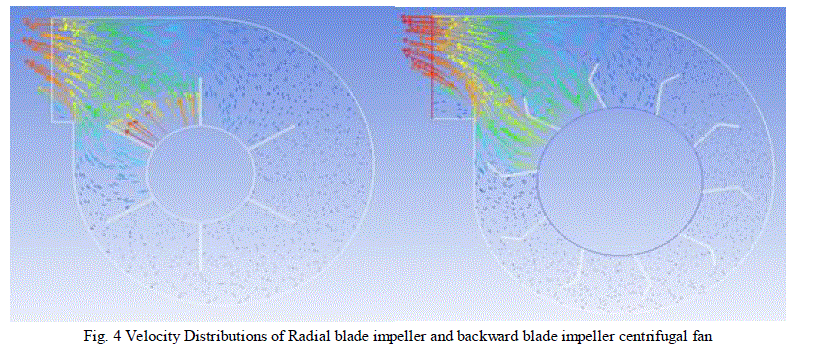
| The velocity distribution, in this part is represented by velocity vectors. This helps to display the velocity value and the direction of fluid around the volute casing and impeller. Figure 4 shows the velocity distribution of fluid around the volute casing and impeller vane for an inlet & outlet. It is found that the velocity values are proportional to the mass flow rate. The velocity become very high after passing through backward blade impeller whereas radial velocity is high near the inlet of impeller and outlet of impeller. A high gradient of fluid velocity appears at the amalgamation of outlet and low gradient of fluid velocity appears at the amalgamation of inlet due to the change of curve. |
 |
| For Centrifugal fan of 260 mm inlet and 250 x 210 mm, the simulation for static analysis was done with a flow-rate of 1750 CFM. As shown in fig 5, the pressure flow-field changes according to the shape of impeller blade. Centrifugal fan inlet velocity taken on the basis of inlet diameter and suction capacity, for radial blade impeller inlet velocity is 15.56 mm/s and for backward blade impeller diameter 360 mm inlet and 250 x210 , velocity taken 8.11 m/s. |
| F. Pressure Distributions |
 |
| After the investigation of flow in the centrifugal fan, it is found that the pressure is a function of both the value of flowrate and the shape of impeller blade. From the above figure 5, it is found that lower pressure is created at the entrance of radialblade impeller inlet which is near to the head of centrifugal fan; therefore it provides the lowest flow rate in this position. Conversely, for the same flow rate condition, higher pressure at the entrance of inlet of backward blade impeller which is near to the head of centrifugal fan, therefore it provides the highest flow rate in this position. |
COMPARISON WITH EXPERIMENTAL RESULTS |
| The results obtained from the CFD analysis of the centrifugal fan system with physical testing are as shown in table VII. |
 |
CONCLUSION |
| The three parameters static pressure (SP in mm of water column), static efficiency, power consumed by fan obtained from the numerical design and CFD analysis are correlated successfully for radial blade impeller and backward blade impeller. Hence it can be concluded that the CFD optimization of volute casing helps numerical procedure in improvement of results. However, the variation of 2-4% is observed due to the assumptions in preparing the numerical procedure and CAD model for it. The k-ε (2 eqn. SST) turbulence model gives more accurate computational solution for the fluid physics. Finally, it can be concluded that the design methodology thus developed for high efficiency centrifugal fan impellers with backward blades which includes numerical design as well as the CFD parametric optimization of Volute casing has been successfully implemented and validated. |
References |
|