ISSN ONLINE(2319-8753)PRINT(2347-6710)
ISSN ONLINE(2319-8753)PRINT(2347-6710)
Anwar S. Siddiqui 1, Naqui Anwer 2, Abdullah Umar 3
|
| Related article at Pubmed, Scholar Google |
Visit for more related articles at International Journal of Innovative Research in Science, Engineering and Technology
The smart grid can be viewed as a digital upgrade of the existing electricity infrastructure to allow for dynamic optimization of current operations as well as incorporate dynamic gateways for alternative sources of energy production. The smart grid is the modern day power transmission system with non conventional energy resources and FACTS controllers. The modern day power transmission system is a network of interconnection which connects systems at intra-regional, inter-regional and national level. Due to deregulation of the power sector, the basic transmission challenge is to provide a network capable of delivering contracted power from power supplies to consumers over a large geographical area. Power transfer in most integrated transmission system is constrained by transient and voltage stability. The power transfer capability of any transmission line largely depends on the reactance of the line keeping the transmission voltages constant. The mismatch of reactance between a group of transmissions lines result in uneven power sharing between them which may cause one or more lines to be overloaded beyond its rating. FACTS controllers can be effectively used to manage the flow of active and reactive powers of transmission systems such that no line is overloaded. This paper discusses the use of Series FACTS controllers in order to change line reactance and phase angle for controlling the power flow in a transmission system.
Keywords |
| Smart grid, transmission line, FACTS controllers, power flow, reactance. |
INTRODUCTION |
| A smart grid is a digitally enabled electrical grid that accommodates attributes from suppliers as well as consumers. The smart grid can be viewed as a digital upgrade of the existing electricity infrastructure to allow for dynamic optimization of current operations as well as incorporate dynamic gateways for alternative sources of energy production. The smart grid is a combination of conventional power system infrastructure with the non conventional energy sources (wind, solar etc) [5], [10]. In the present power scenario the transmission systems are overused due to increased industrial demands and deregulation of the power supply. This necessitates the development of new technologies for maximizing the power transfers of existing transmission facilities while, at the same time, maintaining acceptable levels of network reliability and stability. Recent advancement in power electronics has proven to satisfy this need by introducing the concept of flexible AC transmission system (FACTS). The FACTS controllers are used in regulating the power flows, transmission voltages and mitigate the dynamic disturbance. Since its inception, the FACTS devices has developed in steps, the first generation being mechanically controlled capacitors and inductors. The second generation of FACTS devices replaced the mechanical switches by the thyristor valve control. This gave a marked improvement in the speed and the enhancement in concept to mitigate the disturbances. The third generation exploited the concept of converter based devices. These devices provide multidimensional control of the power system parameters [1], [2]. Power flow in a transmission line can be controlled by regulating the voltage at the two ends of the line, the phase angle or the reactance of the line. Thyristor controlled series compensators works on the principal of regulating the voltage of the transmission line by injecting voltage employing capacitor or inductor. [1] – [4]. This paper is focused on the aspect of changing the reactance of the transmission lines to manage the flow of power through the transmission lines and eliminating the possibility of overloading using series FACTS controllers. |
POWER FLOW IN TRANSMISSION LINES |
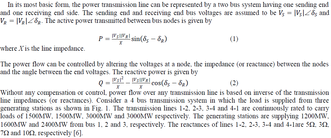 |
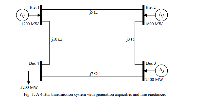 |
| The power flow can be determined by calculating the power flows due to each generating station individually. It can be observed that for each generating station there are two paths for the power flow. The power flow for these two paths can be calculated and tabulated as shown in Table 1 and Fig. 2. |
 |
 |
| It can be observed that there are two paths for the power flow in each case and the power flow is inversely proportional to the reactance (or impedance) offered by that path. Further, it can also be observed that line 3-4 will be overloaded beyond its capacity while other three lines remain under loaded. The overload on line 3-4 can be managed by diverting a part of the line 3-4 power (3168MW) through others lines. From equations (1) and (2), it is evident that by changing the line parameters the load flow can be managed. The flow of power can be managed, such that no transmission line is overloaded, using the FACTS controllers. This paper is focussed on the use of series FACTS controllers, in order to change the line reactance so that power flow through each transmission line remain below its continuous rating and thus overloading can be eliminated. |
FACTS CONTROLLERS : A REVIEW |
 |
| 1. Static Synchronous Series Compensator (SSSC) |
| 2. Thyristor controlled Series Capacitor (TCSC) |
| 3. Thyristor controlled Series Reactor (TCSR) |
| 1. Static Synchronous Series Compensator (SSSC) |
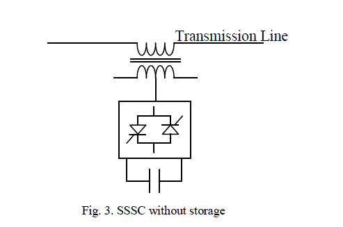
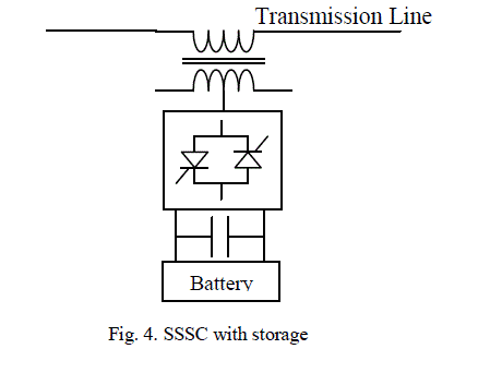
| The SSSC may have two types of configuration – with or without energy storage. In the SSSC configuration without storage (Fig. 3), the output voltage of the device is controlled independently and is 90o out of phase with the line current which changes the overall reactive voltage drop across the line. In general, the series injected voltage is very small compared to the line voltage. When the SSSC is configured with storage (battery) as shown in Fig. 4, it injects a voltage vector of variable angle in series with the line. |
 |
| 2. Thyristor controlled Series Capacitor (TCSC) |
| The TCSC (Fig. 5) consists of a series capacitor bank in parallel with a thyristor controlled reactor (TCR) which provides smooth variable series capacitance control. When the triggering delay angle of TCR is 180o, the reactor becomes non-conducting and the series capacitor has its normal impedance. As the triggering delay angle of TCR is reduced to less than 180o, the capacitive reactance increases. When the triggering delay angle of TCR is 90o, the rector becomes fully conducting, and the total impedance become inductive. |
 |
| 3. Thyristor controlled Series Reactor (TCSR) |
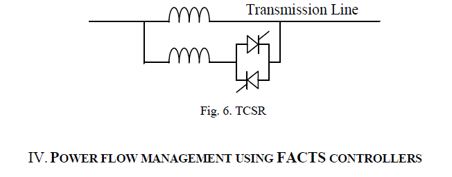
| A TCSR (Fig. 6) consists of a series reactor in parallel with TCR so as to provide smooth variable series reactance control. When the triggering delay angle of TCR is 180o, the reactor becomes non-conducting and the uncontrolled reactor acts as a fault limiter. For the triggering delay angle below 180o, the net inductance decreases until the triggering becomes 90o, at which the inductance value becomes equal to the parallel combination of the two inductances [8],[15]. |
 |
POWER FLOW MANAGEMENT USING FACTS CONTROLLERS |
| It is evident from Fig. 2(d), that line 3-4 is overloaded, while other lines remain under loaded. The proposed solution for eliminating this overloading is to adjust the reactances of the transmission lines by series FACTS controllers. Now, suppose a TCSC (or any other controller) is connected in line 4-1 to provide a variable capacitive reactance of 5. Therefore, the net reactance of line 4-1 will be reduced to 5 as shown in Fig. 7. |
 |
| The power flow for the reconfigured system with FACTS controllers can be calculated in the similar way as shown in Table 2 and Fig. 5. |
 |
| It can be observed that by adjusting capacitive reactance of the controller in line 4-1 at the synchronous frequency to 5, the power flow in the line changes and is shown in Fig. 8. In this way the line 3-4, which was overloaded, can be managed to share load below its continuous rating and the overloading can be eliminated. |
CONCLUSION |
| Smart grid is at the intersection of existing power infrastructure and new communication technologies. The deregulation of electrical energy and more private players in the power sector enforces that the transmission lines must be loaded to their full capacity. It is evident, that the some of the transmission lines in any transmission system are vulnerable to overloading conditions while many of them remain under utilised. The power flow in a transmission line is inversely proportional to their reactance. Therefore, a change in transmission line reactance (or impedance) will cause a change in the power flow in the system. In this paper, it has been proved that by introducing reactance (capacitive) in a transmission line through series FACTS controller, the reactance and thus the power flow can be managed in such a way that no transmission line is overloaded. The FACTS controllers are fully thyristor controlled, therefore, can be operated as many times as required. It is to be noted from the section IV that only one type of series controllers, out of several types discussed in section III, is required to be connected in one line out of all the lines to adjust power flows in a transmission system. |
References |
|