ISSN ONLINE(2319-8753)PRINT(2347-6710)
ISSN ONLINE(2319-8753)PRINT(2347-6710)
MaroofaH. R awoot1, M.F.A.R.Satarkar2
|
| Related article at Pubmed, Scholar Google |
Visit for more related articles at International Journal of Innovative Research in Science, Engineering and Technology
lightning is a major cause of overhead line faults, 5% to 10% of the lightning-strokes causes faults, results in permanent damage to power system equipment. Lightning is a physical phenomenon, which is often seen as a source of destruction causing millions of dollars loss annually.Therefore, it is very advantageous to predict lightning occurrence to avoid the risk of damages to not only electrical and electronics equipment but also to the person. Due to prediction of lightning at least we know the probability of lightning in the form of low, medium and high range by using fuzzy logic system. This paper summarizes the fuzzy inference system (FIS) for the prediction of lightning.
Keywords |
| Lightning; fuzzy logic system; fuzzy inference system. |
INTRODUCTION |
| Lightning is massive electrostatic discharge caused by electric charges in the atmosphere, and resulting in a strike, from a cloud to itself, a cloud to a cloud or a cloud to ground, and accompanied by the loud sound of thunder. Lightning is the main cause of faults and outages in electric power overhead transmission line.The distribution of the lightning is different according to the season and region. Of all lightning discharges only around 25% of the lightning bolt reaches the ground. Lightning flashes cause the reduction into the expected life of the transmission line. The initiation of a flashover across line insulation may occur in response to a severe flash. The lightning which strikes the ground wire of the line can create different pattern of flashover on phase conductors. The patterns are depending on many factors such as lightning current magnitude, front wave time and tail wave time, structure of transmission tower, the position of phaseconductors, tower grounding and striking distance. Worldwide, there are a few thousand lightning deaths and tens of thousands of lightning injuries per year. Lightning initiates many forest fire and over 30% of all electric power failures are lightning related [1]. When lightning strikes a transmission line tower, a travelling voltage is generated which travels back and forth along the tower, which is being reflected at the tower footing and at the tower top, thus raising the voltage at the cross-arms and stressing the insulators. The insulator will flashover if this transient voltage exceeds its withstand level (backflash). In order to reduce the number of flashovers on the lines, there are different methods to improve the lightning performance of lines i.e. improving critical flashover of insulators, reducing grounding impedance, installing shield wire for lines without shield wire and installing lightning arresters. The tower footing resistance is one of factors effected the back flashover voltage across the insulator in transmission system. [2]. |
II. PROPOSED SYSTEM |
| The lightning and its effects are analyzed entirelyby carried out a study in MATLAB environment. It will be covering following tasks. [3] |
| A. Analysis of Lightning • The lightning signal which follows with very high frequency and high voltage/currents is plotted using MATLAB. • The signal values with time are taken from a data set and then its variations are plotted. B. Effect of Tower footing resistance |
| The tower footing resistance and its importance is studied. • Tower footing resistances for different values are analyzed. • Its effects are studied. C. Prediction of Lightning • Here the values based prediction of lightning can be done. • For this, probability based fuzzy forecasting system will be used. • From that the lightning effect can be classified as low, medium and high level of lightning hazard. |
III. FUZZY LOGI C CONTROLLER |
| One of the reasons for the popularity of Fuzzy Logic Controllers is its logical resemblance to a human operator. It operates on the foundations of a knowledge base which in turn rely upon the various if then rules, similar to a human operator. Unlike other control strategies, this is simpler as there is no complex mathematical knowledge required. TheFLC requires only a qualitative knowledge of the system thereby making the controller not only easy to use, but also easy to design. |
| A.Advantages of Fuzzy Logic Controller The advantages provided by a FLC are listed below: • It is simple to design. • It provides a hint of human intelligence to the controller. • It is cost effective. • No mathematical modelling of the system is required. • Linguistic variables are used instead of numerical ones. • Non-linearity of the system can be handled easily. • System response is fast. • Reliability of the system is increased. • High degree of precision is achieved. |
| These advantages allow fuzzy controllers can be used in systems where description of the process and identification of the process parameters with precision is highly difficult. Hence it provides a fuzzy characteristic to the control mechanism. [4] B.Fuzzy Inference System Fuzzy inference systems (FISs) are also known as fuzzy rule-based systems, fuzzy model, fuzzy expert system, and fuzzy associative memory. This is a major unit of a fuzzy logic system. The decision-making is an important part in the entire system. The FIS formulates suitable rules and based upon the rules the decision is made. This is mainly based on the concepts of the fuzzy set theory, fuzzy IF–THEN rules, and fuzzy reasoning. FIS uses âÃâ¬Ãâ¢IF. . . THEN. . . âÃâ¬Ãâstatements, and the connectors present in the rule statement are âÃâ¬Ãâ¢ORâÃâ¬Ãâ or âÃâ¬Ãâ¢ANDâÃâ¬Ãâ to make the necessary decision rules. The basic FIS can take either fuzzy inputs or crisp inputs, but the outputs it produces are almost alwaysfuzzy sets. When the FIS is used as a controller, it is necessary to have a crisp output. Therefore in this case defuzzification method is adopted to best extract a crisp value that best represents a fuzzy set. |
| C.Construction and Working of Inference System Fuzzy inference system consists of a fuzzification interface, a rule base, a database, a decision-making unit, and finally a defuzzification interface. A FIS with five functional blocks is shown in Fig.1. The function of each block is as follows: • A rule base containing a number of fuzzy IF–THEN rules; • A database which defines the membership functions of the fuzzy sets used in the fuzzy rules; • A decision-making unit which performs the inference operations on the rules; • A fuzzification interface which transforms the crisp inputs into degrees of match with linguistic values; and • A defuzzification interface which transforms the fuzzy results of the inference into a crisp output. |
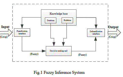 |
| The working of FIS is as follows. The crisp input is converted in to fuzzy by using fuzzification method. After fuzzification the rule base is formed. The rule base and the database are jointly referred to as the knowledge base.Defuzzification is used to convert fuzzy value to the real world value which is the output [5]. The steps of fuzzy reasoning (inference operations upon fuzzy IF– THEN rules) performed by FISs are: 1. Compare the input variables with the membership functions on the antecedent part to obtain the membership values of each linguistic label. (This step is often called fuzzification.) 2. Combine (through a specific t-norm operator, usually multiplication or min) the membership values on the premise part to get firing strength (weight) of each rule 3. Generate the qualified consequents (either fuzzy or crisp) or each rule depending on the firing strength. 4. Aggregate the qualified consequents to produce a crisp output. (This step is called defuzzification.) |
IV.EFFECTOFTOWERFOOTINGRESISTANCEON LIGHTNING IMPULSES |
The tower footing resistance is extremely important parameters in determination of lightning flashover rates. The lower the tower footing resistance, the more negative reflections produced from tower base towards the tower top and these hence help to lower the peak voltage at the tower top [6]. It is defined as; the resistance offered by tower footing to the dissipation of current. Theeffectiveness of a ground wire depends to a large extent on the tower footing resistance. Tower footing resistance of all the towers shall be measured in dry weather after their erection and before the stringing of earth wire.The tower footing resistance can be calculated as [2]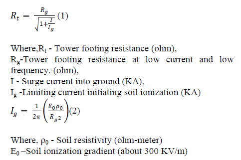 |
| To reduce outage rates and exposure of human life to danger due to lightning strikes, the tower footing impedance must be kept to a minimum. In cases where the tower footing resistance is higher than the standards value (10Ω or less), additional measures may be considered to lower the resistance. Such measures may include use of a vertical or horizontal electrode or even using a special resistance reducing material to achieve a lower tower footing resistance [7, 8] A. Tower Footing Resistance Dependant Factors Tower footing resistance depends on the following factors 1. Type of electrode configuration 2. Soil resistivity ïÃÂö Ground electrode Ground electrode consists of three basic components ground conductor, the connection/bonding of conductor to the ground electrode and ground electrode itself |
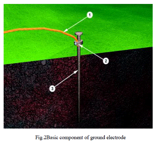 |
| The resistance of a ground electrode has three basic components: A) The resistance of the ground electrode itself and the connections to the electrode. B) The contact resistance of the surrounding earth to the electrode. C) The resistance of the surrounding body of earth around the ground electrode. There are three variables that affect the resistance of a ground electrode and they are as follows 1. The ground itself 2. The length/depth of the ground electrode 3. Diameter of the ground electrode. |
| ïÃÂö Soil Resistivity Soil resistivity and earthing system plays a key role in generation, transmission and distribution for safe and proper operation of any electric power system. Soil resistivity directly affects the design of a grounding system.Soil resistivity is defined as the resistance between the opposite faces of a cube of soil having sides of length one meter and can be expressed in Ohm-meters. Soil resistivity is the key factor that determines what the resistance of the charging electrode will be and to what depth it must be driven to obtain low ground resistance. The resistivity of the soil varies widely throughout the world and changes seasonally. Soil resistivity is determined largely by the content of its electrolyte which consists of moisture, minerals, and the dissolved salt. When selecting the test technique for soil resistivity, factors such as maximum probe depths, lengths of cables required, efficiency of the measuring technique, cost and ease of interpretation of the data need to be considered [9].The Resistivity values for several types of soils and water are shown in Table 1. |
 |
V. SIMULATION RESULTS |
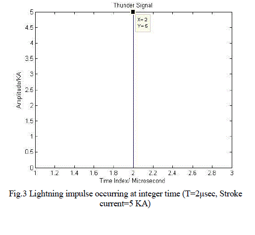
| Basically the simulation results are obtained by using MATLAB software.Fig.3 shows the results for particular time considering time, t=2μsec. |
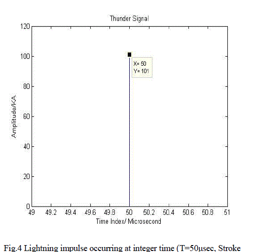
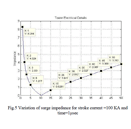
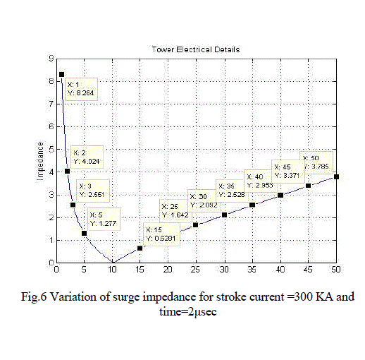
| Fig.4 shows the results for particular time considering time, t=50μsec. Similarly the results are obtained for the calculation of tower footing resistance value for considering stroke current in kilo amperes (KA) and time interval in microsecond (μsec).Here, the variation of surge impedance are also obtained. Fig.5 shows the results for stroke current=100 KA and time=1μsec, then tower footing resistance value can be obtained as Rt=16.5822 Ω and the surge impedance variations are also obtained from the same. Fig.6 shows the results for stroke current=300 KA and time=2μsec, then tower footing resistance value can be obtained as Rt=9.7069Ω and the surge impedance variations are also obtained from the same. |
 |
 |
 |
 |
VI. CONCLUSIONS |
| The above study carried out, shows that, the magnitude of lightning impulse can be obtained for particular time revels that, the value of tower footing resistance will be depend on the particular value of stroke current. The variation of surge impedance is also depend on the magnitude of lightning impulse. The tower footing resistance, moisture and temperature are givenasaninput to the fuzzy inference system. With the help of fuzzy inference system possibility of stroke can be forecasted as an output membership function |
References |
|