ISSN ONLINE(2319-8753)PRINT(2347-6710)
ISSN ONLINE(2319-8753)PRINT(2347-6710)
Rakhi.J.Nair1, S.Manikandan2
|
| Related article at Pubmed, Scholar Google |
Visit for more related articles at International Journal of Innovative Research in Science, Engineering and Technology
FSO uses modulated optical focused beams to establish atmospheric data transmission. This re-emerging technology combines high data rates around 2.5 Gbps in commercial implementations.This characteristic, along with high network reconfigurability (provided by the short deployment time), license-free operation and low sensitivity to electromagnetic interference and jamming, makes FSO systems even more interesting for defense applications. ON-OFF keying (OOK) modulation, used by most FSO systems, is not adequate to logically hide the information, if the beam is intercepted. This scenario should be considered, in the case of long-haul military mobile system with large divergence angles. Other disadvantage is that these systems are vulnerable to atmospheric phenomena, such as attenuation and scintillation. All these factors must be considered during the design of a new FSO system for military purposes.In the proposed system, encoding is done at each relay path to protect the transmitted data from any kind of security attack.Data security in this system comes from the physical signal encoding and decoding processes , because a corresponding process is required to decode the code pattern in order to successfully receive the transmitted data. When the encoding and decoding information is kept secret, the data security is ensured. Physical encoding imposes complex encoding to the physicaly transmitted signals . After the physical encoding, the signal carrying data is transformed to an unpredictable form which is being modulated using PPM modulation
Keywords |
| Atmospheric turbulence; Amplified spontaneous emission; free-space optical communications; Wavelength division multiplexing. Interchannel crosstalk. |
INTRODUCTION |
| ree-space optical (FSO) communication has been successfully used for short-distance transmissions up to 4 km . Compared to optical fiber systems, FSO communication has the advantage of ease of setup , provision of access in difficult terrainsss and lower cost (i.e., no purchasing and installing of fiber) . FSO communication-based systems have advantages over RF (or millimeter-wave) systems such as improved security, no frequency licensing, and higher speed over the short-haul access . Nevertheless FSO communication is faced with considerable challenges such as atmospheric attenuation and turbulence-induced scintillation [7,14]. A WDM access network using FSO communication in the distribution link is a practical proposition, since both FSO systems and optical fiber use similar transmission wavelengths and system components [10,7]. Therefore, the integration of both technologies may yield a cost effective and reliable hybrid optical access network solution. |
| For long FSO propagation distances optical amplifiers (OAs) are necessary. Interchannel crosstalk in WDM systems is well reported [8]. Here the situation changes as atmospheric turbulence in the hybrid networkâÃâ¬ÃŸs distribution link causes a fluctuating crosstalk effect that significantly exacerbates its negative performance strong effect. The turbulence accentuation of interchannel crosstalk occurs when the signal and crosstalk paths are independently turbulent (from being physically completely distinct) such that the crosstalk power may temporarily approach or even significantly exceed the signal power despite a sensible long time average signal-tocrosstalk ratio. The performance is limited when probability of crosstalk power exceeds the signal power (either by increase in turbulence of crosstalk or decrease in turbulence of signal or both). |
SYSTEM DESIGN AND DESCRIPTION |
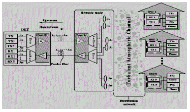
| Basically, a WDM PON connects a number of different wavelength OLT to ONUs over an interconnecting optical fiber system. Block diagram shows a WDM Passive optical network using FSO communication instead of fiber for distribution links which is proposed here. The suboptimal performance of the remote node in the downstream transmission and the imperfection of the OLT demultiplexer in the upstream transmission lead to the undesired wavelength reception of optical signals which is called as interchannel crosstalk. This effect is more severe in the upstream transmission, as it may be exasperated by turbulence, while in the downstream transmission the ONUs can be arranged typically so as to prevent the introduction of further crosstalk at the ONU photo- diode (or an optical filter could optionally be placed before it). Note that in the upstream transmission intrachannel crosstalk can also exist in principle if beam spreading leads to a part of the transmitting power falling within the field of view of an inadvertent collecting lens. This is neglected here because it can generally be avoided by ensuring that Optical network units are not aligned to have near identical transmission paths. |
| A. Upstream Transmission |
| In the upstream, each ONU has a devoted independent point-to-point optical link to the optical line terminal with a laser of its own specific fixed wavelength. The atmospheric channel which is distribution network transmit the signals from the ONUs to a mux.The MUX combines and transmits these signals through a single optical feeder fiber to the optical line terminal. At the OLT the demux separates the multiplexed signals into separate wavelengths. Several WDM mux/demux technologies exist. The AWG (arrayed waveguide grating) based devices are most popular because of their low chromatic dispersion loss. But complexity in production ,high cost and variation in temperature dependent loss are drawbacks [5].The free-space diffraction grating is a promising technology for overcoming the drawbacks of AWG-based devices [2]. The ONU transmitters each transmit optical signals toward corresponding receiver collecting lenses (RCLs).The ONU transmit power is assumed upto 20 dBm and not to exceed this limit, within the maximum possible value according to laser skin and eye safety regulations .The FSO system transmitted powers typically exceed fiber PON ONU transmit powers both because the atmospheric channel is highly attenuating and because it lacks the nonlinear effects that occur in optical fiber. As it approaches the receiver collecting lens, the beam spreads out, characterized by its divergence angle θ, due to diffraction and wave front distortion induced by atmospheric turbulence . Each remote node RCL couples its wavelength through a short length of fiber .An optical preamplifier of gain G and noise figure (NF) can be placed either at the remote node output to increase the signal power through the feeder fiber or can be placed at the demux input to improve the effective OLT receiver sensitivity. After the DEMUX a PIN photodiode with quantum efficiency η is placed . Then amplification of the resulting electrical signal is done and filtered before passing to the decision device, where the threshold is applied. square law detection process is applied for photo detection leading to the ASE- ASE and signal– ASE beat noises. The receiver is assumed with electrical bandwidth |
| B. Downstream Transmission |
| In the downstream, N separate OLT lasers transmit signals belonging to each ONU on a particular wavelength from one point to another. In the performance calculations of downstream, the same assumptions as in the upstream transmission are made for the channel spacing ,optical wavelengths, and the use of optimal threshold in the on– off keyed scheme. However, maximum OLT transmit powers are lower (typically 10 dBm ) inorder to reduce fiber nonlinearity. Interchannel crosstalk in downstream occurs due to imperfection of demux in the remote node , but this is not emphasized by the atmospheric turbulence, since the crosstalk occurs before the distribution link and so it essentially experiences the same atmospheric link turbulence as the signal. |
| C. Optical Amplifier Placement |
| Two different amplifier locations are considered: One at the remote node(Case A) and another at the OLT(Case B). In the upstream Case A, the ASE noise experiences loss due to OLT demux loss and feeder fiber attenuation, while in the Case B of upstream , the ASE noise suffers only from OLT demux loss .In some cases the location of the upstream Optical amplifier may not make much difference to the performance, considering that the optical SNR(signal-to-noise ratio) differs by only about 4 dB between Case A and Case B (for 20 km fiber), which is not significant when OSNR is good. Therefore, the location of upstream amplifier mainly depend on practical issues such as the availability of power at the remote node, which in turn depends on the power of the pointing and tracking system. In the downstream Case A, the ASE noise suffers from atmospheric attenuation, remote node demux loss and beam spreading loss, while in the Case B of downstream, the ASE noise experiences an additional feeder fiber attenuation. As in the case of upstream issues exist regarding amplifier placement, but with the additional need not to provide too much power into the fiber in the downstream Case B due to nonlinearity issues. |
 |
PHYSICAL ENCODING AND DECODING FOR SECURITY |
| FSO uses modulated optical focused beams to establish atmospheric data transmission. This re-emerging technology combines high data rates (around 2.5 Gbps in commercial implementations), characteristic of optical medium, with short deployment time, an advantage of Radio Frequency (RF) systems. In addition, the convergent optical beam presented by FSO (divergence angles of up to 10 mrad), allows the optical links to provide significant degrees of security and immunity to interception. This characteristic, along with high network reconfigurability (provided by the short deployment time), license-free operation and low sensitivity to electromagnetic interference and jamming, makes FSO systems even more interesting for defense applications. Nevertheless, despite the good degree of physical security provided by the convergent beam, ON-OFF keying (OOK) modulation, used by most FSO systems, is not adequate to logically hide the information, if the beam is intercepted. This scenario should be considered, in the case of long-haul military mobile system with large divergence angles. Other disadvantage is that these systems are vulnerable to atmospheric phenomena, such as attenuation and scintillation. All these factors must be considered during the design of a new FSO system for military purposes. |
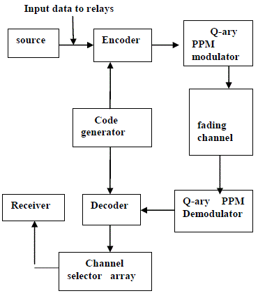 |
| Fig 2.BLOCK DIAGRAM OF THE SYSTEM |
| In this work, encoding is done at each relay path to protect the transmitted data from any kind of security attack.Data security in this system comes from the physical signal encoding and decoding processes , because a corresponding process is required to decode the code pattern in order to successfully receive the transmitted data. When the encoding and decoding information is kept secret, the data security is ensured. Physical encoding imposes complex encoding onto the physical transmitted signals . After the physical encoding, the signal carrying data is transformed to an unpredictable form which is being modulated using PPM modulation. When the transformed signals are transmitted through optical links, the adversary cannot intercept the data directly from the transmitted signals without the corresponding physical decoding process. |
| A.Hadamard Code Generator |
| Physical encoding is implemented through Hadamard code generator.It generate Hadamard code from orthogonal set of codes. The Hadamard Code Generator block generates a Hadamard code from a Hadamard matrix, its rows form an orthogonal set of codes. This codes can be used for spreading communication systems in which the receiver is perfectly synchronized with the transmitter. In these systems the codes are decorrelated completely therefore the despreading operation is ideal. |
| The Hadamard codes are the individual rows of a Hadamard matrix. These are square matrices whose entries are +1 or -1, and its rows and columns are mutually orthogonal. The N-by-N Hadamard matrix, denoted HN, is defined recursively if N is a nonnegative power of 2,. The Nby- N Hadamard matrix has the property that HNHN T = NIN where IN is the N-by-N identity matrix. Hadamard matrices are matrices of 1's and -1's whose columns are orthogonal, H'*H = n*I where [n n]=size(H) and I = eye(n,n) .They have applications in several different areas, including signal processing ,combinatorics, and numerical analysis. The simulation covers an end-to-end system showing the encoded signal, channel model, demodulation of the received signal and reception |
| Q-ary PPM |
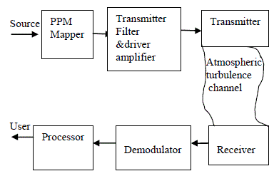
| Fig.3 represent the block diagram of QPPM system which transmits L=log2Q bits per symbol, providing high power efficiency. In the transmitter, the signals described by the binary data bits are converted into a stream of pulses corresponding to QPPM symbol. At the receiver, after signal detection (the demodulator block) and de-interleaving, channel decoding is performed. The demodulation operation is done based on the received signal light intensity. |
 |
| The electrical signal after the optical or electrical conversion is: |
| re=η(I+Ia)+n (1) |
| where I is the light intensity of received signal, Ia is the remaining ambient light intensity after frequency and spatial filtering and η is the optical or electrical conversion efficiency. n is the sum of dark, thermal, and shot noise. We assume that the ambient light can be almost perfectly cancelled. So, the received signal after the cancellation of the ambient light, before demodulation is: |
| re =ηI+n (2) |
| We suppose that the receiver is thermal noise limited, and consider n as a zero-mean Gaussian additive noise of variance σn 2, independent of the signal I. Let Ts denote the symbol duration and No the noise unilateral power spectral density. Taking into account the low-pass filtering of bandwidth 1/2Ts after photo-detection, the noise variance equals σn 2= N0/2Ts. We further consider the received signal intensity I as the product of I0, the emitted light intensity, and h, the channel atmospheric turbulence such that: |
| I = h IO (3) |
FADING CHANNEL MODELLING |
| The reliability of the communication link can be determined if we use a good probabilistic model for the turbulence. To design a high-performance communication link for the atmospheric free-space optical (FSO) channel, it is of great importance to characterize the channel. Several probability density functions (PDFs) have been proposed for the intensity variations at the receiver of an optical link. The atmospheric turbulence impairs the performance of an FSO link by causing the received optical signal to vary randomly thus giving rise to signal fading. |
| A. Rayleigh Distribution |
| The Rayleigh model is used to describe the channel gain. The degree of fading or scintillation index for the Rayleigh situation is 1.The density function of Rayleigh is more concentrated at low (deeply faded) values. |
| The PDF of path gain or channel fading amplitude „a „for Rayleigh distribution is: |
| fA(a) = 2ae-a^2 (4) |
| B. Lognormal Distribution |
| The Lognormal model is used for weak turbulence conditions or less severe fading. The pdf of the path gain or channel fading amplitude „aâÃâ¬ÃŸ is given as : |
 (5) (5) |
| where the parameters μ denotes mean and σ2 denotes variance.μ and σ should satisfy the relation μ = -σ2 so that the mean path intensity E[A2]=1. |
| Typical values of scintillation index (S.I) ranges between 0.4 and 1. |
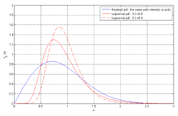 |
| Fig.4 shows the probability density functions of both Rayleigh and Log-normal fading. In particular two values for the scintillation index (S.I.) were taken for the Log-normal case. Analyzing the pdfs, it would be clear that low values of ‘a’ have a higher density in the Rayleigh case than that of the Log-normal case and this certainly imposes more fading on the system performance. |
CHANNEL SELECTOR ARRAY |
| The channel selector array consists of a hit crossing unit , an upcounter and corresponding switch.The Hit Crossing block detects when the input reaches the Hit crossing offset parameter value in the direction specified by the Hit crossing direction property. If the input signal is exactly the value of the offset value after the hit crossing is detected, the block continues to output a value of 1. If the input signals at two adjacent points bracket the offset value (but neither value is exactly equal to the offset), the block outputs a value of 1 at the second time step.If the input signal is constant and equal to the offset value, the block outputs 1 only if the Hit crossing direction property is set to either. |
| The Counter block increments or decrements an internal counter each time it receives a trigger event at the Inc/Dec port. A trigger event at the Rst port resets the ounter to its initial state.The input to the Rst port must be a real, samplebased scalar. The input to the Inc/Dec port can be a real, sample-based scalar, or a real, frame-based vector (that is, a single channel). The Counter block operates in frame-based mode when the Inc/Dec input is a frame-based vector. the block increments or decrements the counter by the total number of trigger events contained in the Inc/Dec input frame. Thus, the counter may change multiple times during the processing of a single Inc/Dec input frame. When the block has a hit port, it outputs a value of 1 if any of the specified Hit values match any of the counter values during the processing of the Inc/Dec input frame. |
EXAMPLE RESULT |
| Consider the example of a FSO Metropolitan Area Network as shown in Fig.5. Consider three neighboring buildings (1), (2) and (3) and assume that a FSO connection is available between each building and its two neighboring buildings. In FSO networks, each one of these connections is established via FSO-based wireless units each consisting of an optical transceiver with a transmitter and a receiver to provide full-duplex capability. |
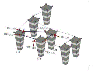 |
| Given the high directivity and non-broadcast nature of FSO transmissions, one separate transceiver is entirely dedicated for the communication with each neighboring building. We assume that the transceivers on building (2) are available for cooperation to enhance the communication reliability between buildings (1) and (3). By abuse of notations, buildings (1), (2) and (3) will be denoted by source (S), relay (R) and destination (D), respectively. The cooperation strategy is depicted in Fig.6. |
| It is worth noting that the transceivers at (R) are not deployed with the objective of assisting (S). In fact, these transceivers are deployed for (R) to communicate with (S) and (D); if (R) is willing to share its existing resources (and (R) has no information to transmit), then it can act as a relay for assisting (S) in its communication with (D). |
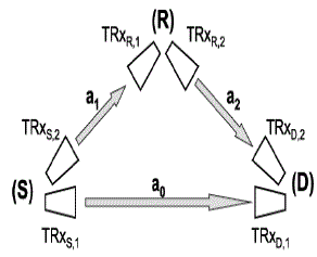 |
| The cooperation strategy is as follows: a sequence of symbols is first transmitted to the relay. At a second time, (R) transmits the decoded symbols to (D) while (S) transmits the same symbol sequence simultaneously to (D). Since three transmissions are involved in each cooperation cycle, then the transmitted power from transceivers TRxS,1, TRxS,2 and TRxR,2 must be divided by 3. |
CONCLUSION |
| In new paradigms of war, such as Network Centric Warfare (NCW), increasing flow of information is necessary in order to provide strategic superiority and, in consequence, increased combat power. As network-centric solutions started to be thought for military systems, increasing data rates showed to be necessary and Free Space Optics (FSO) technology appeared as a good solution. |
References |
|