International Journal of Innovative Research in Science, Engineering and Technology
ISSN ONLINE(2319-8753)PRINT(2347-6710)
ISSN ONLINE(2319-8753)PRINT(2347-6710)
Mohammed Ali Khalifa1, Kamal Mohamed Saied1,Sami Salem Bitro1, Miftahul Anwar2 and Muhammad Nizam3
|
| Related article at Pubmed, Scholar Google |
Visit for more related articles at International Journal of Innovative Research in Science, Engineering and Technology
This paper demonstrates the comparative study between Boost and Cuk DC-DC converter using maximum power point tracking (MPPT) incremental conductance (ICA) algorithm. cuk converter use for comparative. Few parameters such as voltage, current and time response at different combination has been measured. Matlab simulink software was applied for performance evaluation on energy point. Simulation was considered different solar irradiance and temperature variations. And simulation results showed that cuk converter better than boost in terms of time responsee and the ripple voltage.
Keywords |
| maximum power point tracking, MPPT, photo voltaic, PV, direct current, DC DC Introduction |
INTRODUCTION |
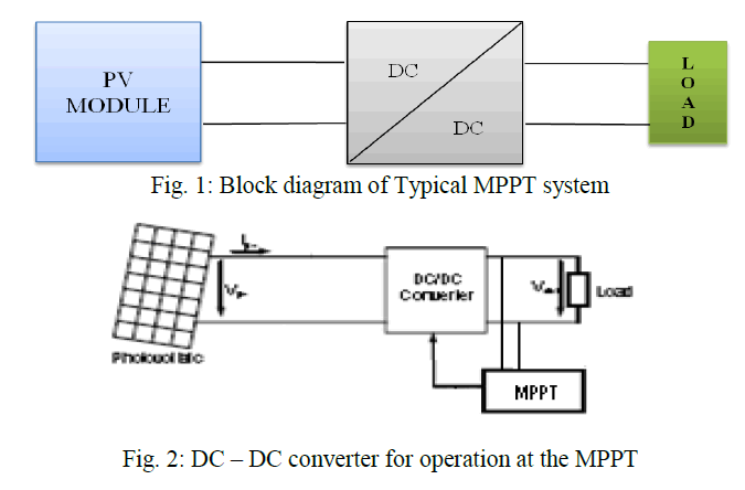
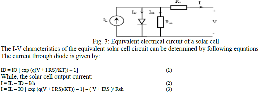
| The thrive increasing in the demand for electricity and the recent change in the environmental behaviour such as global warming shift to need for a new source of energy that is cheaper and sustainable with less carbon emissions. Solar energy has offered promising outcomes in the quest of finding the solution to the problem. The harnessing of solar energy using PV modules comes with its own problems that arise from the change in an insulation conditions. These changes in insulation conditions significantly affect the efficiency and output power of the PV modules [1],[3]. A great deal of research has been done to improve the efficiency of the PV modules. A number of methods of how to track the maximum power point of a PV module have been proposed to solve the problem of efficiency and products using these methods have been manufactured and are now commercially available for consumers [1],[3]. As the market is now flooded with varieties of these MPPT that are meant to enhance the efficiency of PV modules under various insulation conditions it is not known how many of these can really deliver on their commitment under a variety of field conditions. This research then looks at how a different type of converter affects the output power of the module and also investigates if the MPPT that are said to be highly efficient and do track the true maximum power point under the various conditions [1]. A MPPT is used for extracting the maximum power from the solar PV module and transferring that power to the load [4], [5]A dc/dc converter (step up/ step down) serves the purpose of transferring maximum power from the solar PV module to the load. A dc/dc converter acts as an interface between the load as shown in figure 1 [5]. By changing the duty cycle the load impedance as seen by the source is varied and matched at the point of the peak power with the source as to transfer the maximum power[5]. Therefore MPPT techniques are needed to maintain the PV array’s operating at its MPP [6]. Many MPPT techniques have been proposed in the literature. e.g , the Perturb and Observe (P&O) methods [4],[6]. Incremental Conductance (IC) methods [7], [8],[10] Fuzzy Logic Method [2], [4], [6], [9], etc. In this paper two most popular of MPPT technique (Perturb and Observe (P&O) methods and Incremental Conductance methods) and three different DC-DC converter (Buck, Boost and Cuk converter) will involve in comparative study Figure (2) [11] |
 |
| Few comparison such as voltage, current and power out put for each different combination has been recorded. Multi changes in duty cycle, temperature by keeping voltage and current as main sensed parameter been done in the simulation. The DC converter techniques will be compared, by using Matlab tool Simulink, considering the variant of circuit combination. |
BASIC THEORY |
A. PV ARRAY |
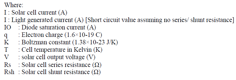
| A solar panel cell basically is a p-n semiconductor junction. When exposed to the light, a DC current is generated. The generated current varies linearly with the solar irradiance The equivalent electrical circuit of an ideal solar cell can be treated as a current source parallel with a diode as shown in figure 3. |
 |
 |
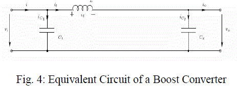
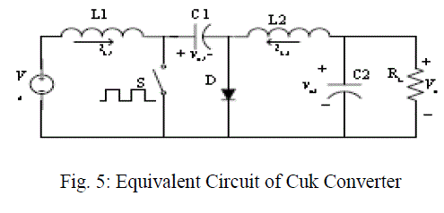
B. BOOST AND CUK DC-DC CONVERTER |
Boost Converter |
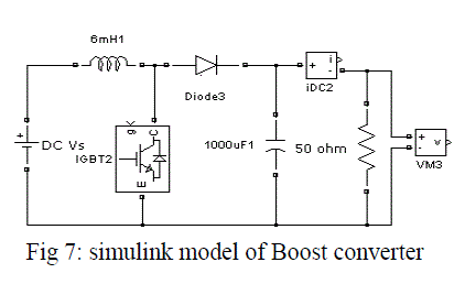
| The boost converter is also known as the step-up converter. The name implies it’s typically application of converting a low input-voltage to a high out-put voltage, essentially functioning like a reversed buck converter shown in figure 4 |
 |
 |
METHODS |
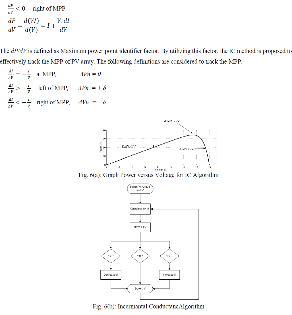
| This block is simulated using the Simulink blocks available in the MATLAB library.And the CUK and Boost converters which are built using the SimPower Systems module of MATLAB. The block diagram for the model shown in Figure (7&8). Incremental conductance algorithm as shown in Fig. (9) is implemented for maximum power point tracking In this method. |
 |
RESULT AND DISCUSSION |
| Results for every converter have been recorded to make sure the comparison of the circuit can be determined accurately. The input, output, voltage, and current is the main comparison to take into consideration. The complexity and simplicity of the circuit have been determined based on the literature. Convergence speed, hardware required and range of effectiveness. |
A. PV Panel Simulation |
| The figure (10(a) ) below illustrates the P-V Curve of PV Module at different Irradiation where X- axis has been symbolized by voltage (volt) range and Y- axis has been demonstrated by power (watt) level. Besides, The performance of PV cell has been depicted at different sub-division irradiation power level. Infact, The pink, blue, green, violet curve represents the irradiation power level at 1000, 750, 500, 250 w/m2 respectively. |
 |
| On whole, It can be said that both output current and power are directly proportional with changes in solar irradiation as expected from the model. Furthermore, The maximum output power as well as current of the module reduced to half when the solar irradiation droped to 500 W/m2. However, the open circuit voltage did not change significantly. |
B. Results of Converter Simulation |
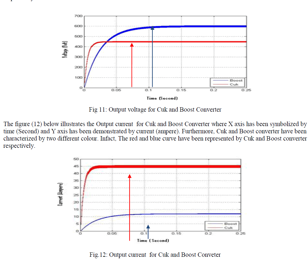
| The figure (11) below illustrates the Output voltage for Cuk and Boost Converter where X axis has been symbolized by time (Second) and Y axis has been demonstrated by power (watt). Furthermore, Cuk and Boost converter have been characterized by two different colour. Infact, The red and blue curve have been represented by Cuk and Boost converter respectively. |
 |
| The figure (11) below illustrates the voltage ripple for Boost Converter where X axis has been symbolized by time (Second) and Y axis has been demonstrated by voltage (volt). Furthermore, the outcome of Boost converter has been characterized by blue colour. |
 |
COMPARISON BETWEEN BOOST AND CUK CONVERTER |
| The percentage between theoretical value and experimental value has been obtained from the simulation result. Theoretical value has been calculated from the basic equation of converters. Meanwhile the experimental value has been acquired from the simulation result using matlab simulink software. From the simulation findings, it was found that that the voltage input for both controller was the same battery (150 VDC). Additionally, at the very beginning of time respond both the converter soared up and afterwards these two converter shifted into stable stage which was same during the whole time counted. The significant mark of both converter has been point out table 1 (below) on the basis of outcome from figure 11-14. |
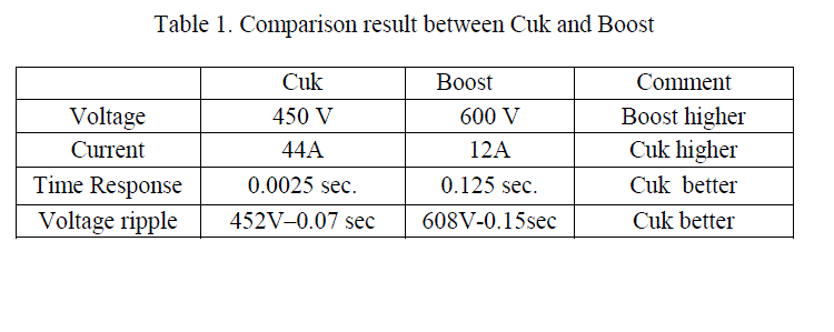 |
| From the comparison result, it can be remarked that the execution of Cuk converter was always better in case of all criteria than Boost converter except voltage result. Additionally, on the stability establishment point of view, finally it can be commented that cuk is better than boost converter. |
CONCLUSION |
| This paper has applied ICA and MPPT algorithm for the comparison between Cuk and Boost converter. The comparison result showed that the Cuk converter better over Boost converter because of (1) the achievement of stability voltage / current is only 0.025 second, while it took 0.12 second in terms of Boost, (2) voltage ripple is also smaller than Boost which is (11.48-11.53) and (14.8-15.2) amp respectively. It can be concluded that Cuk converter better than Boost in time response and the ripple voltage as shown Table 1. |
References |
|