ISSN ONLINE(2319-8753)PRINT(2347-6710)
ISSN ONLINE(2319-8753)PRINT(2347-6710)
Kanakarathinam.P1, Manikandan.M2
|
| Related article at Pubmed, Scholar Google |
Visit for more related articles at International Journal of Innovative Research in Science, Engineering and Technology
The stability of Fixed Speed Induction Generator (FSIG) based wind turbines can be improved by a Static Synchronous Compensator (STATCOM). Under unbalanced grid voltage dips, the negative sequence voltage causes heavy generator torque oscillations that reduce the lifetime of the drive train. In this project, investigations on a Fixed Speed Induction Generator based wind farm in combination with a Static Synchronous Compensator under real and reactive power compensation. A Static Synchronous Compensator control structure with the capability to coordinate the control between the positive and the negative sequence of the grid voltage is proposed. The results clarify the effect of the positive and the negative sequence voltage compensation by a Static Synchronous Compensator on the operation of the Fixed Speed Induction Generator based wind farm with first priority, the Static Synchronous Compensator ensures power compensation ride through enhancement of the wind farm.
Keywords |
| STATCOM, FSIG, Wind Farm, Real and Reactive power, Compensation |
INTRODUCTION |
| Wind power is the conversion of renewable energy into suitable energy resources. Such as using wind turbines to generate electricity, windmills for mechanical power, wind pumps for water pumping, or sails to propel ships. The total amount of economically extractable power available from the wind is considerably more than present human power use from all sources. Wind power, as an alternative to fossil fuels, is abundant, renewable, widely spread, clean, and produces no greenhouse gas emissions during operation. Wind power is the world‘s rapid growing source of energy. The majority of electricity is generated by burning coal, rather than more eco friendly methods like hydroelectric power. This use of coal causes untold environmental damage through CO2 and other toxic emissions. The energy sector is by far the biggest source of these emissions, both in the India and globally, and if we are to tackle climate change it is clear we need to move away from burning limited fossil fuel reserves to more sustainable and renewable sources of energy. Wind power has many advantages that make it a lucrative source of power for both utility-scale and small, distributed power generation applications. The beneficial characteristics of wind power include: Clean and endless fuel: Wind power doesn‘t produces any emissions and is not run down with time. A one megawatt (1 MW) wind turbine for one year can displace over 1,500 tons of carbon dioxide, 6.5 tons of sulphur dioxides, 3.2 tons of nitrogen oxide, and 60 pounds of mercury (based on the U.S. average utility generation fuel mix). Local financial development: Wind plants can provide a firm flow of income to landowners who lease their land for wind development, while increasing property tax revenues for local communities. |
| Modular and scalable technology: Wind applications can take many forms, including large wind farms, distributed generation, and single end-use systems. Utilities can use wind resources tactically to help reduce load forecasting risks and trapped costs. Reduced dependence on imported fuels: Wind energy expenditures don‘t need to obtain fuels from abroad, keeping funds closer to home, and lessening reliance on foreign governments that supply these fuels. |
| In the early 1980s, the government of India established the Ministry of Non-Conventional Energy Sources (MNES) to promote diversification of the country's energy supply and satisfy the ever-increasing energy demand of its rapidly growing economy. In 2006, this ministry was renamed as the Ministry of New and Renewable Energy (MNRE). During the first decade of the 21st century, India emerged as the 2nd leading wind power market in Asia. Currently, its cumulative installed capacity is close to 13 GW, with the market growing at an average rate of over 20% over the past 3 years. More than 2,100 MW wind capacity projects were added in the financial year 2010–11. The installed capacity increased from a modest base of 41.3 MW in 1992 to reach 13,065.78 MW by December 2010. |
| Modern wind power technology has come a long way in the last two decades, both globally and in India. Improved technology has slowly and steadily improved capacity efficiency. A key trend in the Indian industry is the development of multi megawatt turbines installed at greater hub heights. Larger diameter rotors enable a single wind power generator to capture more energy or power per tower. This allows WTGs to take advantage of higher altitudes with stronger winds and less turbulence (wind speed generally increases with height above the ground). Subsequently larger machines have resulted in a steady increase in the capacity factor on average from 10-12% in 1998 to 20-22% in 2010. For two decades now, global average WTG power ratings have grown almost linearly, with present commercial machines rated on average in the range of 1.5 MW to 2.1 MW. |
II.REAL AND REACTIVE POWER |
| Real power is product of the voltage across a branch of an alternating current circuit and the component of the electric current that is in phase with the voltage. The average value over time of the instantaneous power of alternating current. The real power depends on the acting values of the voltage and strength of the current. Reactive power is the power that supplies the stored energy in reactive elements. Power, as we know, consists of two components, active and reactive power. The total sum of active and reactive power is called as apparent power. In circuits, energy is stored temporarily in inductive and capacitive elements. The Inductors (reactors) are said to store or absorb reactive power, because they store energy in the form of a magnetic field. Capacitors are said to generate reactive power, because they store energy in the form of an electric field. Therefore when current passes through the capacitor, a charge is built up to produce the full voltage difference over a certain period of time.The main reason for reactive power compensation in a system is |
| 1. The voltage regulation. 2. Increased system stability. 3. Better utilization of machines connected to the system. 4. Reducing losses associated with the system 5. To prevent voltage collapse as well as voltage sag. |
| The impedance of transmission lines and the need for lagging VAR by most 18 machines in a generating system results in the consumption of reactive power, thus affecting the stability limits of the system as well as transmission lines. Unnecessary voltage drops lead to increased losses which needs to be supplied by the source and in turn leading to outages in the line due to increased stress on the system to carry this imaginary power. Thus we can infer that the compensation of reactive power not only mitigates all these effects but also helps in better transient response to faults and disturbances. In recent times there has been an increased focus on the techniques used for the compensation and with better devices included in the technology, the compensation is made more effective. It is very much required that the lines be relieved of the obligation to carry the reactive power, which is better provided near the generators or the loads. Shunt compensation can be installed near the load. |
| Power Generation and Transmission is a complex process, requiring the working of many components of the power system in tandem to maximize the output. One of the main components to form a major part is the reactive power in the system. It is required to maintain the voltage to deliver the active power through the lines. Loads like motor loads and other loads require reactive power for their operation. To improve the performance of power systems, we need to manage this real and reactive power in an efficient way and this is known as real and reactive power compensation. There are two aspects to the problem of reactive power compensation load compensation and voltage support. Load compensation consists of improvement in power factor, balancing of real power drawn from the supply, better voltage regulation, etc. of large fluctuating loads. Voltage support consists of reduction of voltage fluctuation at a given terminal of the transmission line. Two types of compensation can be used. There are series and shunt compensation. These modify the parameters of the system to give enhanced VAR compensation. In recent years, static VAR compensators like the STATCOM have been developed. These quite satisfactorily do the job of absorbing or generating reactive power with a faster time response and come under Flexible AC Transmission Systems (FACTS). This allows an increase in transfer of apparent power through a transmission line, and much better stability by the adjustment of parameters that govern the power system i.e. current, voltage, phase angle, frequency and impedance. |
III.SYSTEM CONFIGURATION |
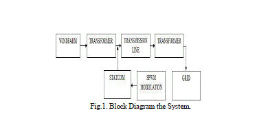
| The block diagram contains the wind farm model, transformer, STATCOM, controller model of STATCOM, and the grid lines. The 20 megawatts wind model is coupled with the transformer. The STATCOM model is coupled with transformer for the purpose of the real and reactive power compensation. The STATCOM model is connected to three phase circuit breaker, when the breaker is in ON period, the real and reactive power will compensate. For that period, the STATCOM performance can be analyzed. The block diagram of the system is shown in Fig.1. |
 |
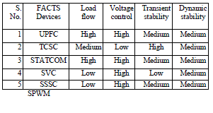
| The STATCOM model is a subsystem of the system. The Subsystem block can represent a virtual subsystem or a non virtual subsystem. The primary difference is that non virtual subsystems provide the ability to control when the contents of the subsystem are evaluated. Non virtual subsystems are executed as a single unit by the Simulink engine. A subsystem is virtual unless the block is conditionally executed. The sinusoidal pulse width modulation technique is applied to the STATCOM controller model. The sinusoidal pulse width modulation to control the fundamental line to line voltage. The sinusoidal pulse width modulation is containing the adder circuit and gate devices. The gate devices are get triggering pulse, the devices in operation condition and adder circuit is gives the signal in SPWM model. The sinusoidal pulse width modulation is producing the sine waves. Flexible AC transmission systems (FACTS) controllers have been mainly used for solving various power system steady state control problems. FACTS devices are capable of controlling the active and reactive power flows in a transmission line by controlling its series and shunt parameters. The FACTS devices is compared the factors is Load flow, Voltage control, Transient stability, and Dynamic stability. The STATCOM is very convenient compared to other devices |
 |
| In single-pulse and multiple pulse modulation techniques the width of all pulses are same but in sinusoidal pulse width modulation the width of each pulse is varied in proportion to the amplitude of a sine wave. In this technique the gating signals are generated by comparing a sinusoidal reference signal with a triangular carrier wave. The DF and LOH are reduced significantly. The output voltage is obtained from the matlab results. The DF and LOH are measured by using FFT analysis. |
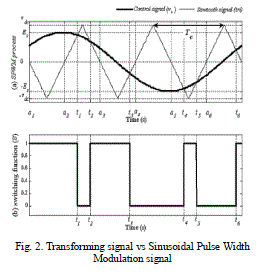 |
| The gating signal for the inverter is obtained by taking the repeating sequence (triangular wave) as the control signal and Comparing it with the reference wave (sinusoidal wave).In order to detect or eliminate the zero sequence currents we use zero hold circuit and by comparing the with the help of greater than or equal to blocks. The sine wave is compared with a triangle wave (carrier wave) and the instantaneous value of the triangular wave is less than that of the sine wave, the PWM output signal is in high level. Otherwise it is turned into the low level (0). The SPWM process is explained and the corresponding switching function is shown in Fig.2. A high carrier frequency directly improves the reproduction of the original signal. |
IV.RESULT ANALYSIS |
| The proposed wind system is containing the static synchronous compensator model. The static synchronous compensator is compensating the real and reactive power, this model. The parameter of the wind model voltage, current, and speed is regulated condition. |
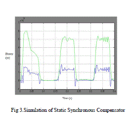 |
| The above simulation model is the static synchronous compensator is connected in proposed model. The proposed model is compensating the real and reactive power. The Three phase circuit breaker is ON period, the static synchronous compensator model is ON condition, the real and reactive power is compensated in the wind model. The simulation time taken only 0.4s. The power comspensates time period is 0.08s to 0.16s and 0.24s to 0.32s. The three phase circuit is OFF period, the static synchronous compensator model is OFF condition, the real and reactive power is uncompensated in the wind model. The uncompensated time period is 0.01s to 0.07s, 0.16s to 0.24s and 0.32s to 0.38s. |
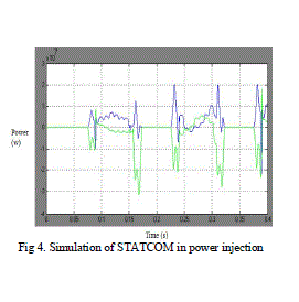 |
| The simulation of static synchronous compensator in power injection mode in the grid lines. The three phase circuit breaker is connected in the static synchronous compensator. The three phase circuit is ON period, the static synchronous compensator is ON condition, the real and reactive power is inject in wind model. The power inject in the wind model is time taken is 0.7s to 0.16s and 0.22s to 0.32s. The three phase circuit breaker in OFF period, the static synchronous compensator is OFF condition, the real and reactive power is absorbs in the static synchronous compensator. The time is taken in this mode operation is 0.16s to 0.22s, 0.32s to 0.4s. The proposed model simulation of the static synchronous compensator in connected in the wind model. The twenty wind turbine is connected in wind model. The nominal speed and initial speed of wind model is 11 m/s. The simulation is including the voltage, current and speed of the wind model. |
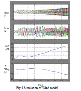 |
| The voltage, current and speed of the fixed speed wind generator coupled with wind turbine are regulated in the wind model. The DC voltage of the wind generation system during load conditions is regulated condition. The static synchronous compensator is connected in the wind model; the real and reactive power is compensated in the grid lines. |
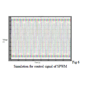 |
| The fig 6 shows the control signal of sinusoidal pulse width modulation waveform is applied in the static synchronous compensator model. The Sinusoidal Pulse Width Modulation is generating sine wave in static synchronous compensator model The benefits of utilizing proposed system in electrical transmission systems can be summarized as follows |
| 1. Better utilization of existing transmission system assets 2. Increased transmission system reliability and availability 3. Increased dynamic and transient grid stability and reduction of loop flows 4. Increased quality of supply for sensitive industries 5. Environmental benefits Better utilization of existing transmission system assets. |
V. CONCLUSION |
| A voltage control structure for a Static Synchronous Compensator (STATCOM) at a Fixed Speed Induction Generator (FSIG) based wind farm under grid voltage condition has been analyzed. The proposed structure is containing the STATCOM model. The STATCOM model is controls the real and reactive power in the wind turbine model. The novel contribution of this project lies in the coordination of the real and reactive power control by the STATCOM.To, while Sinusoidal Pulse Width Modulation (SWPM) technique used in the STATCOM model and the related effect on the wind turbine behaviour. While the real and reactive power compensation leads to an increased voltage stability of the wind farm, increasing the lifetime of the generator drive train. The coordination is realized by prioritizing the real and reactive power compensation of the STATCOM control. If there is remaining wind farm voltage, current and power is controlled. |
References |
|