ISSN ONLINE(2319-8753)PRINT(2347-6710)
ISSN ONLINE(2319-8753)PRINT(2347-6710)
| Phagna Esha Singh1, Siddhakar Bhumi2, Rami Monika3 U.G. Student, Department of Biomedical Engineering, Government Engineering College, Gandhinagar, Gujarat, India1 |
| Related article at Pubmed, Scholar Google |
Visit for more related articles at International Journal of Innovative Research in Science, Engineering and Technology
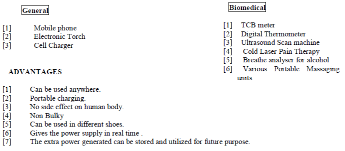
With the extend use of technology, it has been the vital function to develop something new in both software and hardware. A worn out battery or a lost charges are the two difficulties every electronic device user undergoes through. To overcome this we, the biomedical engineering students, have proposed a new technology to adopt charging of these portable electronic devices with the help of human walking. Walking is the best and common activity in day to day life. As per the study of biomechanics, we came to realize that ground reaction force (GRF) exerted from the foot, when converted into voltage gives enough power supply to run a device. While walking the person loses some energy from foot in the form of vibrations which are sensed and converted into electric form. Piezoelectric crystal does the work of generating output out of foot moment. Piezoelectric materials have the capability of absorbing mechanical energy from surroundings, especially vibrations and transform it into electric energy that can be used as power supply in real time to other appliances like mobile phones, power banks, various small handy biomedical instruments etc. This project can be implemented while jogging in the morning, gym, walking on trade-mill, in dense populated areas like railways, bus stands, etc
Keywords |
| battery, bio energy, biomechanics, generation, ground reaction force , GRF, Piezo electric crystal, power supply, portable units, walking,. |
I. INTRODUCTION |
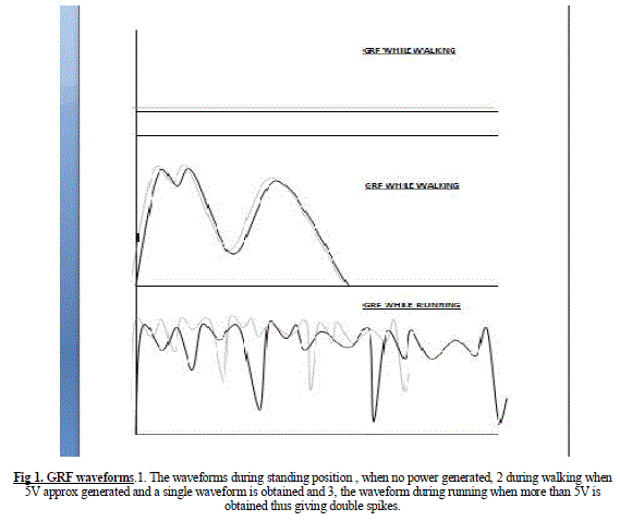
| The world’s energy consumption is at an all the time high with the demand continuously increasing. With the advent use of portable machines in this technological world; it has become a major issue of power source. The situation brings up several challenges that need to be addressed. 1.) Power supply. 2.) Battery discharging. 3.) Availability of power source. End with turning off the machine without battery In Biomechanics, the ground reaction force, GRF is the force exerted by the ground on the body in contact with it. For example ,a person standing motionless on the ground exerts a contact on it which is equal to the person’s weight and at same time an equal and opposite GRF is exerted by the ground on the person .Thus, as the human starts walking, this GRF increases which generates power in greater amount as shown in figure 1 The utilization of waste energy of foot power with human locomotion is very much relevant for highly populated countries where the roads, railway stations, bus stands, temples, etc. The human bio-energy being wasted if it can be made possible for utilization it will be very useful energy sources. |
 |
| Although small electronic devices are mostly powered by batteries, there are an increasing number of wireless sensors using energy harvesters instead of the batteries. For consumer electronic devices, there are different emerging technologies that are under research or in commercialization stages. Harvesting energy from humans is particularly useful for not only common people, but also for soldiers’ portable electronic equipment. These harvesters produce energy from human’s kinetic energy, thermal energy or body biological processes energies and they can benefit soldiers by decreasing the carrying load, patients by increasing the lifetime of the devices and reducing the number of surgeries to change the battery of the devices and consumer electronics users by providing a green and endless source of energy. In future, it could be more beneficial for a lot of applications especially for consumer electronic devices. The energy scavenging fruman’s temperature has been studied and it was shown that it is capable to produce a very limited amount of energy that cannot charge any device properly. Thus, the energy harvesting with biological sources like walking is our main goal. |
II. RELATED WORK |
| 1).Qingguo Li, Veronica Naing and J Maxwell Donelan” Research Development of a biomechanical energy harvester” |
| Journal of Neuro Engineering and Rehabilitation. The goal was effectively harvesting energy from walking, by making a small light weight device that efficiently converts intermittent, bi-directional, low speed and high torque mechanical power to electricity, and selectively engages power generation to assist muscles in performing negative mechanical work.d |
| To achieve this, this device used a one-way clutch to transmit only knee extension motions, a spur gear transmission to amplify the angular speed, a brushless DC rotary magnetic generator to convert the mechanical power into electrical power, a control system to determine when to open and close the power generation circuit based on measurements of knee angle, and a customized orthopaedic knee brace to distribute the device reaction torque over a large leg surface area. |
| The device selectively engaged power generation towards the end of swing extension, assisting knee flex or muscles by producing substantial flexion torque (6.4 Nm), and efficiently converted the input mechanical power into electricity (54.6%). Consequently, six subjects walking at 1.5 m/s generated 4.8 ± 0.8 W of electrical power with only a 5.0 ± 21 W increase in metabolic cost. Due to a lower angular velocity, peak stance extension torque and peak mechanical power were both smaller than in swing extension (3.3 Nm and 5.5 W, respectively). The average mechanical power for a complete cycle was 4.4 W. |
| 2). Hamid Abdi and Navid Mohajer “Human Passive Motion and a User-friendly Energy Harvesting System” |
| This paper discussed existing methods of energy harvesting from humans body motion and introduced a novel system for harvesting energy from abdominal motion. The harvester was designed by integrating a PVDF piezoelectric transduced with a normal pants belt after calculating the maximum strain region of the belt. The system including piezoelectric transducer was modelled by MATLAB and the results showed that it can provide up to 1.2mW in rest time and 2.3mW after mild exercise time. This amount of energy is sufficient to power an mp3 player or IMD. |
III. FINAL STAGE |
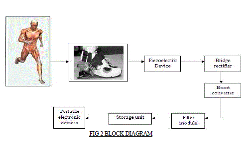
| One of the most suitable methods for obtaining the energy from surrounding is using piezo electric crystal. Piezo electric crystal is one of small scale energy sources. The piezo electric crystals when subjected to vibration they generate a very small voltage, commonly known as piezoelectricity. It has a crystalline structure that converts an applied vibration into a electrical energy. Piezoelectric fibre composite can be connected in series with the capacitors and resistors to reduce or smooth a high voltage input produced by PFCB. For test purposes, the finger tapping was used to flick the tip of the piezo electric crystal of metal disc type, in order to provide the initial disturbance. The testing was done using a multi-meter, and oscilloscope, connected to each other properly to obtain voltage readings as the tapping is done. The first test for voltage output depended on time variation and was conducted without any mass placed on it. This was followed by a second test with the foot step of different masses that were placed on the piezo electric metal disc to observe the output voltage levels. As the more mass that is added on the tip, The more time passes until vibration of the sensor stops. The voltage from the piezo electric metal disc increases depending on the mass and force applied to the tip of the sensor. The following fig 2 shows the block diagram of our project. Each block is explained in detail. |
 |
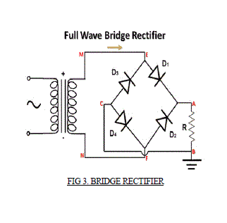
| Bridge rectifier: Due to the vibrations, a piezoelectric crystal generates the electrical power. The produced output voltage is in the form of AC. Then it can be converted to DC by passing it through Rectifier circuit. The converted DC voltage can be fed into Boost converter. As shown in the figure, the bridge rectifier circuit is working in positive half cycle. |
 |
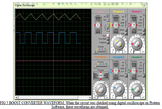
| Boost converter: A boost converter (step-up converter) is a power converter with an output DC voltage greater than its input DC voltage. It is a class of switching-mode power supply (SMPS) containing at least two semiconductor switches (a diode and a transistor) and at least one energy storage element. Filters made of capacitors (sometimes in combination with inductors) are normally added to the output of the converter to reduce output voltage ripple. |
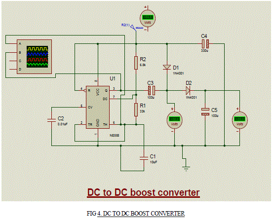 |
| As shown in the figure 4 the internal resistors act as a voltage divider network, providing (2/3) Vcc at the non-inverting terminal of the upper comparator and (1/3) Vcc at the inverting terminal of the lower comparator. In most applications, the control input is not used, so that the control voltage equals + (2/3) VCC. Upper comparator has a threshold input (pin 6) and a control input (pin 5). Output of the upper comparator is applied to set (S) input of the flip-flop. Whenever the threshold voltage exceeds the control voltage, the upper comparator will set the flip-flop and its output is high. To change the output of flip-flop to low, the voltage at the trigger input must fall below + (1/3) Vcc. When this occurs, lower comparator triggers the flip-flop, forcing its output low. The low output from the flip-flop turns the discharge transistor off and forces the power amplifier to output a high. These conditions will continue independent of the voltage on the trigger input. Lower comparator can only cause the flip-flop to output low. From the above discussion it is concluded that for the having low output from the timer 555, the voltage on the threshold input must exceed the control voltage or + (2/3) VCC. This also turns the discharge transistor on. To force the output from the timer high, the voltage on the trigger input must drop below +(1/3) VCC. This turns the discharge transistor off. A voltage may be applied to the control input to change the levels at which the switching occurs. When not in use, a 0.01 nano Farad capacitor should be connected between pin 5 and ground to prevent noise coupled onto this pin from causing false triggering. |
 |
| Filter module: The rectified voltage from the rectifier is a pulsating dc voltage having very high ripple content. But this is not we want, we want a pure ripple free dc waveform. Hence a filter is used. Different types of filters are used such as capacitor filter, LC filter, Choke input filter, π type filter. Figure below shows a capacitor filter connected along the output of the rectifier and the resultant output waveform. |
 |
| Storage unit: It is basically a power bag which stores the charge generated by the piezoelectric and charge the other portable electronic devices |
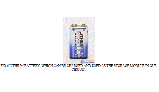
| -Lithium- Ion Battery As shown in fig 7, Pure lithium is very reactive. It reacts vigorously with water to form lithium hydroxide and hydrogen gas. Thus, a non-aqueous electrolyte is typically used, and a sealed container rigidly excludes water from the battery pack .Lithium-ion batteries are more expensive than Ni Cd batteries but operate over a wider temperature range with higher energy densities, while being smaller and lighter. They are fragile and so need a protective circuit to limit peak voltages. |
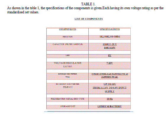
| As shown in the table 1, the specifications of the components is given.Each having its own voltage rating as per the standardised set values. |
 |
IV. ACKNOWLEDGMENTS |
| We have opportunity to say thank them all who have helped us directly or indirectly to make the project successful which is “REAL TIME BATTERY CHARGING SYSTEM BY HUMAN WALKING”. The way can’t walk itself. We have to walk on it. For that we must have a guide. Many guides have contributed to the successful completion of the project. We would like to place on record my grateful thanks to each one of them who help me in this project. We would like to thank our Head of Department , Mr. J.B.VYAS for providing us with suitable media performance, a platform to show our potential and a chance to prove our skills by the way of project development. We would like to thank our parents & friends for giving us full feedback when we are in trouble. I am sincerely thankful to Ms. RUTU NAYAK (Internal Guide) and the whole staff of biomedical engineering departments of Government Engineering College, their extensive help and for providing valuable information, suggestions, and inputs at various stages of work. They helped us to understand the whole project and conceptualized the idea of the project |
REAL TIME APPLICATIONS |
 |
V. CONCLUSION |
| 5V output is obtained while walking which is later boosted up by the DC to DC boost converter .This boost converter gives the 8-9V voltage output ,which can be used to charge the mobile phone (requiring 3.7V) in real time .Thus, in all we conclude that with this process, we can extract the energy from the human feet, convert it into electric energy and use it in real time application of charging the devices. |
References |
|