ISSN ONLINE(2319-8753)PRINT(2347-6710)
ISSN ONLINE(2319-8753)PRINT(2347-6710)
Harisha.S1, Dr. Y.J. Suresh2
|
| Related article at Pubmed, Scholar Google |
Visit for more related articles at International Journal of Innovative Research in Science, Engineering and Technology
A rotor dynamic model is developed by using finite element method (FEM), The rotor includes impellers, bearings and seals.The object of the analysis is to calculate the critical speeds of a rotor to find out if there are sufficient margins of separation between critical speed and the rotor operating speed. Lateral resonant frequencies can excite on the rotor and result in high damaging rotor vibration. The torsional critical speed of rotating machinery components is an important consideration in defining the operational reliability of the rotary equipment train. Pump is mainly a 4 staged centrifugal pump, the modal analysis of the centrifugal pump is performed using ANSYS workbench is used as a FEA tool to find critical speeds or rotor natural frequencies. To meet the higher target of power, machines have to run at higher speeds then pump shaft will be subjected to higher lateral and torsional vibrations because of gyroscopic effect and centrifugal force of the rotating elements mounted on the shaft. The resonance is produced when the rotor natural frequency coincides with operating frequency, the deflection of the rotor will be maximum. To avoid resonance condition, it is necessary to evaluate all stiffness and damping coefficients of wear rings, mechanical seals, throttle seals and bearings. In this work an attempt is made to evaluate the Lateral critical speeds using ANSYS software by plotting Campbell diagrams and is compared with theoretical calculations and RBTS (Rotor Bearing Testing Software). It is very difficult to eliminate all interference points in the system since there are so many external excitations. The rotor has been designed and analyzed by using the guidelines as per API 610 standards.
Keywords |
| Resonance, Modal analysis, Vibration, Rotor dynamics, Centrifugal pump, FEM, API. |
INTRODUCTION |
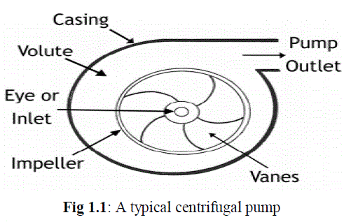
| A centrifugal pump converts the input power to kinetic energy in the liquid by accelerating the liquid by an impeller. The energy created by the pump is kinetic energy according the Bernoulli Equation. Fluid enters the pump through the eye of the impeller which rotates at high speed. The fluid is accelerated radially outward from the pump casing. A vacuum is created at the impellers eye that continuously draws more fluid into the pump To ensure the safety of the pump and associated plant components, the vibration and noise must be kept within certain limits. Typical reasons for pump failures can be diagnosed well in advance by applying the right kind of vibration testing, analysis, and evaluation criteria during pump monitoring or troubleshooting. |
 |
| Basic working of Centrifugal Pump: |
| In a centrifugal pump, energy is imparted by centrifugal force – that is, the force generated by the rotation of an object. This force drives outwards from the centre of rotation. The pump consists of an impeller rotating inside a pump casing. Water enters at the centre, or eye, of the impeller and is flung out to the periphery (the outer edge of the casing) by centrifugal force as the impeller rotates. The water is collected inside the pump casing and discharged from the pump outlet. A centrifugal pump is ideally suited for fire fighting work because it: |
| 1. gives a steady flow |
| 2. operates at variable pressure depending on need |
| 3. is simple in construction and operation |
| 4. is easily maintained and less likely to be damaged by bad pump operation |
| 5. is able to pump dirty or gritty water with minimal damage to the pump |
| 6. is small and compact |
| 7. allows flow to be interrupted without stopping the engine |
| 8. can be connected to an internal combustion engine by direct drive |
| 9. They have no valves, pistons or plungers |
MODEL FORMULATION |
| The lateral analysis is only concerned with the rotor part of the pump. The coupling between pump gear and motor is flexible so the gear and motor are not considered in the calculation and modeling. The details about rotor geometry, impellers mass, bearing properties and material properties are extracted from an existing model and the model is developed in ANSYS |
| 1. Rotor Modeling: SOLID186 is a higher order 3-D 20-node solid element that exhibits quadratic displacement behavior. The element is defined by 20 nodes having three degrees of freedom per node: translations in the nodal x, y, and z directions. The element supports plasticity, hyperelasticity, creep, stress stiffening, large deflection, and large strain capabilities |
| 2. Modeling of Impellers: MASS21 is used to formulate the impellers mass and inertia effects in the rotor. MASS21 is a point element and it is defined by a single node. The degrees of freedom of the element can be extended up to six directions: translations in the nodal x, y, and z directions and rotations about the nodal x, y, and z axes, the rotary inertia effects to the element is included in the element. The mass element adds only mass without any change in stiffness, contribute kinetic energy only. |
| 3. Modeling of Bearings And Supports: There are two bearings in the centrifugal pump that supports the rotor system in its lateral direction. The rotor is supported by mechanical structures like Hub wear rings, eye wear rings, central sleeve and throttle sleeve which acts as bearings. All bearings are modeled as linear isotropic bearings using COMBIN14 element. |
| 4. Loads: An unbalance distribution is assigned to the various parts of the rotor to study the unbalance response. These unbalances are represented as forces which are acting mutually perpendicular to the spinning axis. |
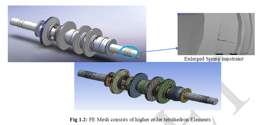
| `5. Constraints: All nodes at axial position are constrained axially and torsionally to avoid axial and twisting of the rotor respectively. The nodes at supports have displacement only in its represented plane (YZ plane). Therefore these nodes are also constrained in axial and torsional direction. The base nodes are fixed in all direction to represent that the model is connected to the rigid base. The FE model of the centrifugal rotor is shown in figure 1.2 |
 |
METHODOLOGY |
| `The present work is mainly concerned with Critical speed analysis of centrifugal pump using ANSYS WORKBENCH. FE modeling consists of complete rotor assembly. |
| 1. LATERAL ANALYSIS: An accurate model of a rotor system is a model that permits accurate calculation of the actual rotor system’s dynamic characteristics. This occurs when the rotor’s mass elastic (inertia-stiffness) properties are adequately represented. |
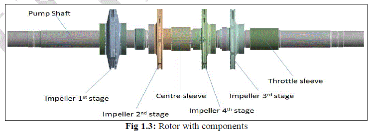
| Solid stepped shaft of the pump is created using SOLIDWORKS considering all small features like fillets and chamfers. End bearings consists of radial ball-ball bearing at both drive and non-drive ends whose stiffness is assumed to have infinite value range due to the fact that the bearing and shaft are in metal contact with each other. |
| Pump is driven my constant speed motor and both of these shafts are connected through coupling. Since the coupling is of flexible type, the rotor is modelled taking in to account only the pump shaft |
 |
| 2. TORSIONAL ANALYSIS: Train-both pump rotor and motor shaft which connected using flexible couplings. The coupling between pump gear and motor is flexible so the gear and motor are considered in the calculation and modeling. The details about rotor geometry, impellers mass, bearing properties and material properties are extracted from an existing model and the model is developed in ANSYS. Wet impeller mass and inertia are assumed to be 20% of dry impeller mass and Inertia. Mass and inertia of impellers, sleeves and other components are considered in the model |
 |
FEA TOOLS USED |
| In this project the pump rotor is considered, which is composed of sub components such as Impeller, rotating sleeves, wear rings etc..and the tool used in this analysis are Ansys 14.0. The following fig shows the 3D model of centrifugal pump.It mainly consists of components like are rotor (shaft), Impellers, Centre sleeves, throttle sleeve, eye and hub wear rings |
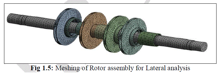
| Meshing of FEA model of Rotor assembly: After successful creation of 3D model, it is meshed with the 3D elements as shown in below figure for both lateral and torsional analysis. |
 |
RESULT AND DISCUSSIONS |
| Calculation Cases |
 |
| A. Lateral analysis Results |
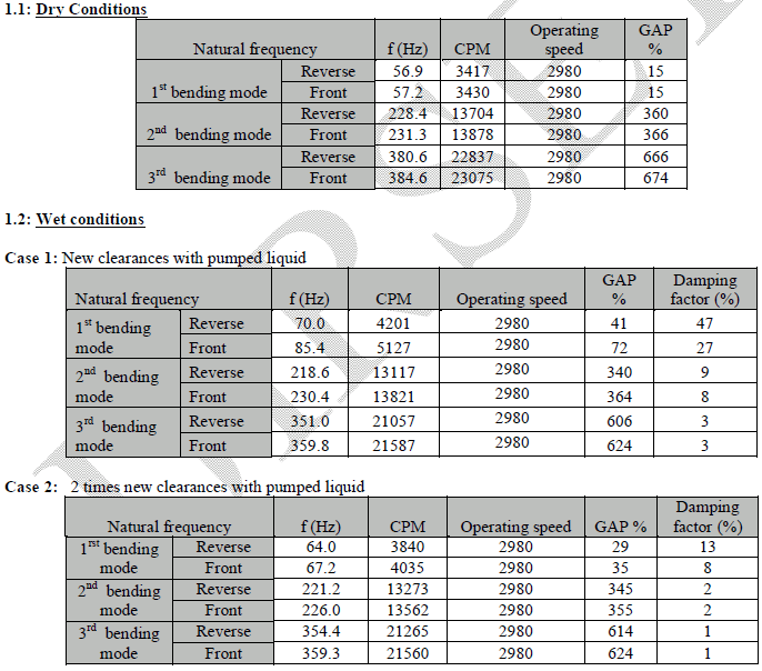
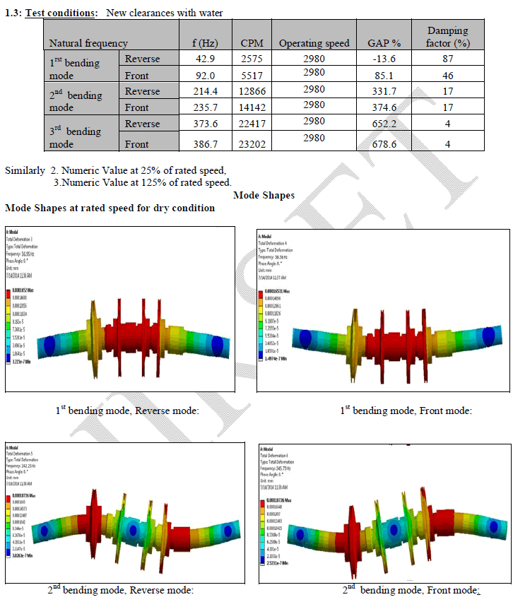
| 1.Numeric Value at rated speed (100%) |
 |
 |
 |
 |
CONCLUSION |
| Lateral Analysis: |
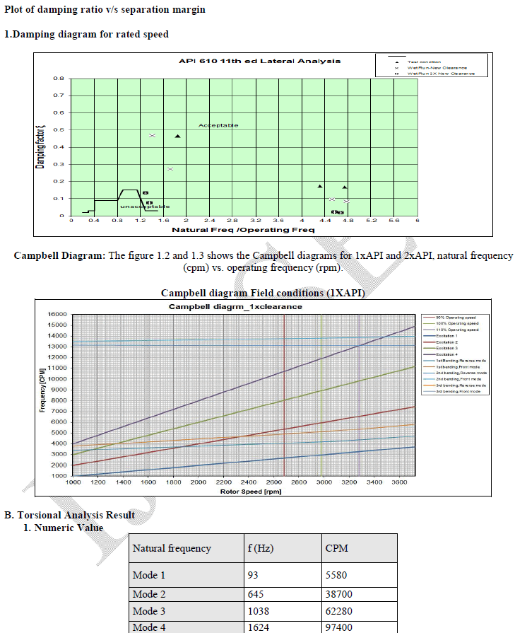
| This analysis demonstrates that from new clearances to two times new clearances, the damping factor versus separation margin between any natural frequency and the synchronous run line are within the acceptable region defined in API 610 last edition. From the Campbell diagrams of all conditions, there is no resonance observed during the speed of 25% of operating speed to 125% of operating speed. The pump is not disturbed by any critical speeds during running. The shaft design is safe based on above calculations. |
| Torsional Analysis: |
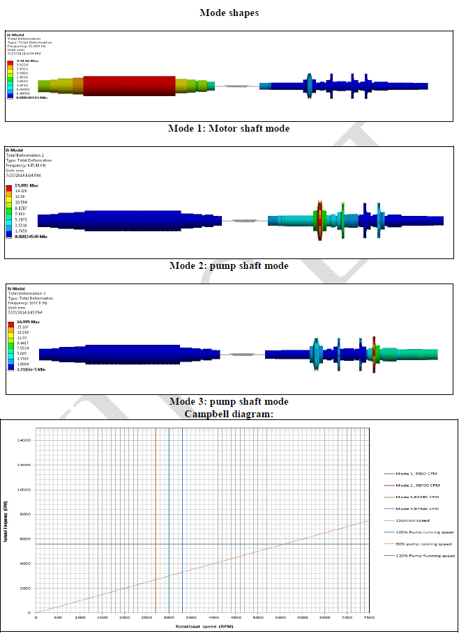
| This dynamic analysis of the rotor shows that the pump shaft, the coupling and the motor shaft as one unit are free from any torsional critical speed according to the API 610 11th edition criterion. The shaft line is rightly designed. |
ACKNOWLEDGEMENT |
| I would like to thank, Dr.Y.J.Suresh. Professor & PG Co-ordinator, Dept. of mechanical engineering, JNNCE, Shimoga. For his valuable support to carry out this work. |
References |
|