ISSN ONLINE(2319-8753)PRINT(2347-6710)
ISSN ONLINE(2319-8753)PRINT(2347-6710)
A.Ramya Sree1, Tavanam Venkata Rao2
|
| Related article at Pubmed, Scholar Google |
Visit for more related articles at International Journal of Innovative Research in Science, Engineering and Technology
Frequency is one of the important parameters to be intercepted for the hostile radars. Digital instantaneous frequency measurement (DIFM) receiver is the mostly used frequency receiver in EW system. The main concern of the DIFM Rx is: Low sensitivity, Low frequency accuracy and fails to handle simultaneous (time overlapped) signals. Sensitivity refers to the minimum RF level at the input of the receiver channel. To do this, a decision making process must take place. The decision is the crossing of a voltage threshold set at a level above the noise floor, representing the number of decibels above random noise that a voltage, signal or noise must attain to assure a certain false alarm rate. The setting of threshold is an important factor in establishing the receiver operating sensitivity, since the higher it is set to reduce false alarms, the greater the signal amplitude necessary to be recognized as a signal to be processed. The proposed design aims to find out the method to improve the Constant False Alarm Rate detector performance by increasing the threshold value and simultaneously enhancing the sensitivity of the system. This technique will be analyzed in MATLAB and implemented on FPGA based digital board through VHDL.
Keywords |
| DIFM, Sensitivity, Noise suppression, Frequency Receivers. |
INTRODUCTION |
| Receiver sensitivity is the lowest power level at which the receiver can detect an RF signal and demodulate data. Sensitivity is purely a receiver specification and is independent of the transmitter. As the signal propagates away from the transmitter, the power density of the signal decreases, making it more difficult for a receiver to detect the signal as the distance increases. Improving the sensitivity on the receiver (making it more negative) will allow the radio to detect weaker signals, and can dramatically increase the transmission range. Sensitivity is vitally important in the decision making process since even slight differences in sensitivity can account for large variations in the range. So this project deals with receiver sensitivity enhancement. |
| The objective of the project is to enhance the sensitivity of the DIFM. In this project receiver sensitivity enhancement is done by using quad phase correlator instead of a single phase correlater which was used in existing regular DIFM. The quad phase correlator is the combination of four correlators. As we are using four corelators, they suppress the effects of noise more efficiently and improve frequency accuracy. It can be used to detect the sensitive signals up to -60dbm |
| The task of the radar designer is to establish the threshold such that the radar target detection goals can be met with a Signal to Noise Ratio (SNR) that is consistent with the capabilities of the radar design with the enhanced Sensitivity. |
| To do this, a decision making process must take place. The decision is the crossing of a voltage threshold set at a level above the noise floor, representing the number of decibels above random noise that a voltage, signal or noise must attain to assure a certain false alarm rate. |
| The setting of threshold is an important factor in establishing the receiver operating sensitivity, since the higher it is set to reduce false alarms, the greater the signal amplitude necessary to be recognized as a signal to be processed. In order to enhance the Sensitivity, the setting of threshold value must be low. A low threshold will allow processing of weaker signal at the penalty of false alarms, which may or may not be useful depending upon the capability of the system to average over many crossings. The objective of the project is to enhance the sensitivity of the system. The technique used here is noise suppression. This technique will be analyzed in MATLAB and implemented on FPGA based digital board. |
Literature Survey |
| The extensive application of EM spectrum to Communication, Radar and Navigation provided the armed forces with powerful tools. Radio Communication provided coordination between forces, radio navigation gives accurate location of the deployed forces and radar performed surveillance of the battle space to verify force deployments and detect hostile forces. The EM spectrum is so extensively exploited, today without its use; the survivability of armed forces is jeopardized. ES also known by ESM involve actions taken to search, intercept, locate, record and analyze radiated EM energy. The information is employed for threat recognition and to use it in tactical employment in EA equipment. The ES function is for real time use, whereas ELINT receivers are used for intelligence collection, which can be subsequently used. ELINT receivers perform fine grain analysis of emitters of interest. If the data cannot be analyzed, it can be stored and analyzed at a later time. |
| EW receivers generally measures quantitatively the following parameters |
| a) Frequency |
| b) Angle of Arrival (AOA) or DF (Direction Finding) |
| c) Pulse width (PW) |
| d) Time of Arrival (TOA) |
II. FREQUENCY RECEIVERS INTRODUCTION |
| Electronic support (ES) system in electronic warfare (EW) involves actions tasked by or under direct control of an operational commander to search for, intercept, identify and locate source of intentional and unintentional radiated electromagnetic energy [1]. Each instantaneous non-communication signal intercepted by the Electronic support system must be characterized by a set of parameters. These parameters provide information required to associate a set of signals belonging to a particular emitter and to identify that emitter among all other emitters whose signals have been intercepted. The parameters generally measured by the Electronic support system for a signal are RF frequency, pulse amplitude, pulse width, time of arrival and angle of arrival. Also, in some systems, polarization of the input signal is measured. Frequency receiver measures the RF frequency precisely and provides the information on the emitted signal i.e. pulse, CW, chirp. |
| Present day battlefield electromagnetic environment is generally very complex with many emitters in the form of pulse trains effectively interleaved, so that before any use can be made of the receiver output, the pulse trains must be deinterleaved. This process involves, identifying each pulse with its particular emitter parameters to isolating each pulse train. Frequency is one of the important parameters to be intercepted for the hostile radars. It is necessary that the Frequency Measurement Receiver must provide very good accuracy and resolution for Pulse train identification. Also Frequency Accuracy is essential when the receiver is used for measurements on spread spectrum signals. |
 |
III. PRINCIPLE OF OPERATION |
| An IFM receiver use delay line to compare the phase of the input signal to measure its frequency. A sinusoidal wave Acos (ωt) is split into two paths, one path delayed by constant value τ with respect to the other. The phase difference between the delayed and un-delayed waves is given by [4] |
 |
| Where E and F are phase-detected voltages proportional to the input phase difference. From which phase angle is determined using |
| θ = tan -1 (E/F) = ω τ |
| Amplitude information in E and F equations over the dynamic range are made constant through a Limiting Amplifier used in front of the power divider. The phase discriminator outputs E and F are amplified and given to Analog to Digital Converter to get the frequency information in digital form. |
| The frequency accuracy depends upon the number of digitizer bits for the phase measurement. It is not possible to get more than 6 bits from digitizer due to phase noise present in the angle information. Six bit data limits the resolution of DIFM. To overcome this limitation more number of channels is used to get the high resolution in parallel. The longest delay line will determine the frequency resolution, when parallel channels are used, where phase measurement > 2π are involved ambiguity in measurement arise. These ambiguities are resolved using shortest delay channels. The shortest delay line is made to measure measurements for < 2π angle coverage. By choosing the appropriate delay ratio and after resolving the ambiguity, desired frequency resolution would be obtained. |
IV. CONFIGURATION OF DIFM RECEIVER |
| The DIFM design is based on the latest development taking place in the field of microwaves and digital electronics to take the best advantage of both the fields. The principle of operation is same as in conventional DIFM receiver, but the DIFM is discussed here incorporates homodyne front end with delay lines, phase comparator using analog IC, phase quantizer using high speed ADC and the frequency resolving and processing circuits are implemented in FPGA. The homodyne based DIFM have advantages over the conventional direct DIFM, like phase information transferred to single IF signal, low frequency IF amplifiers, filters and phase detector can be used for frequency measurement. The DIFM consists of |
| A. Homodyne front end with delay line assembly |
| B. Phase detector |
| C. Phase Quantizer |
| D. Ambiguity resolver |
| To get the desired frequency accuracy DIFM is designed using 5 parallel channels with 5-delay line. |
| D. Ambiguity Resolver |
| The data from L 1 channel is unambiguous and the phase data from remaining higher order delay line having ambiguity. The purpose of the ambiguity resolver circuit is to resolve the ambiguity that is there in the data from L 2 , L 3 , L 4 and L 5 delay line phase discriminator. The ambiguity resolving and frequency processing circuits are being implemented in FPGA, which provides flexibility of reprogramming for any modification in the design without changing physical hardware. The FPGA also has provision for correcting the final frequency data for systematic and non-systematic error in the fastest possible way. Ambiguity resolving circuit is having four stage of processing The reference data is taken from the higher delay line i.e. L 5 data and algorithm proceeds with data from the previous delay line till all the ambiguities are resolved. An IFM receiver has potential of being used in EW systems because it can cover very wide bandwidths, can provide finefrequency resolution on short pulsed signals, and has moderately high sensitivity. One extremely attractive factor of IFM receivers is their very simple structure; therefore, the receivers can be made very compact, an important factor of EW applications. |
V. CONCEPT OF /CONVENTIONAL DIGITAL IFM (DIFM) TECHNIQUE |
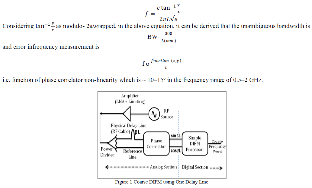
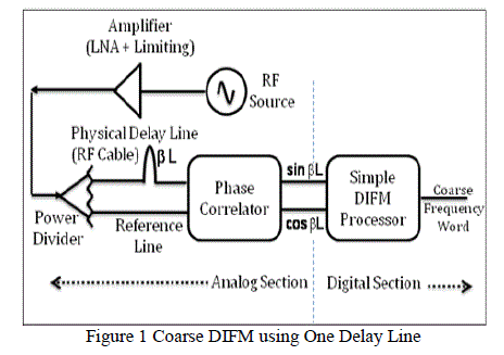
| The simple coarse DIFM technique [4] using single physical delay line is shown in Figure 1. The RF signal of frequency f is generated from RF source. The RF signal after conditioning through proper amplifier is passed through power divider. |
| The two outputs of power divider are connected to analog phase correlators with two different physical RF cables of length difference L (which in turn causes phase difference of (βL).The phase-correlators an analog passive device which takes two input RF signals with phase difference βL radian and provides dc output as ïÿýïÿý = cos ïÿýïÿýïÿýïÿý and ïÿýïÿý = sin ïÿýïÿýïÿýïÿý. |
| A simple DIFM processor does phase-to-frequency operation to measure frequency using two parameters: cos βL and sin βL coming from phase-correlator [4,7,11]. |
 |
| As ferr is inversely proportional to L, so longer the delay line length, higher is the frequency measurement accuracy. But at the same time, bandwidth is also inversely proportional to L. So longer delay line length results in lower bandwidth of operation. Hence for a required bandwidth, if the delay line used is longer than that specified, it results in phase ambiguity (in turn frequency ambiguity).This shows that DIFM with single physical delay line is not adequate to provide high accuracy and wide bandwidth at the same time. Hence there is a necessity to use multiple delay lines, as shown in Figure 1, where longest delay line is used to provide fine frequency accuracy and shorter delay lines are used to resolve the ambiguities to get wide bandwidth of operation. It is to be noted here that DIFM processing which includes ambiguity resolution and also phase-to-frequency conversion, is not as simple as one using one delay line. |
VI. PROPOSED METHODOLOGY |
| The objective is to enhance the sensitivity of the DIFM. In this project receiver sensitivity enhancement is done by using quad phase correlator instead of a single phase correlater which was used in existing regular DIFM. The quad phase correlator is the combination of four correlators. As we are using 4 corelators, they suppress the effects of noise more efficiently and improve frequency accuracy. It can be used to detect the sensitive signals up to -60dbm |
| The task of the designer is to establish the threshold such that the received frequency is achieved even in -60dbm and more signal strength. |
| To do this, a decision making process must take place. The decision is the crossing of a voltage threshold set at a level above the noise floor, representing the number of decibels above random noise that a voltage, signal or noise must attain to assure a certain false alarm rate. |
| The setting of threshold is an important factor in establishing the receiver operating sensitivity, since the higher it is set to reduce false alarms, the greater the signal amplitude necessary to be recognized as a signal to be processed. |
| In order to enhance the Sensitivity, the setting of threshold value must be low. A low threshold will allow processing of weaker signal at the penalty of false alarms, which may or may not be useful depending upon the capability of the system to average over many crossings. |
| To enhance the sensitivity of the DIFM system, we are processing the receiver signal as follows. |
| As usual the signal is receiver from the antenna. Then the received signal is passed through the signal conditioning devices. Then the signal is spitted into two ways using two way power divider. Here one signal is directly consider for the further processing and the other signal is delayed according to the required length. As ferr is inversely proportional to L, so longer the delay line length, higher is the frequency measurement accuracy. But at the same time, bandwidth is also inversely proportional to L. So longer delay line length results in lower bandwidth of operation. Hence for a required bandwidth, if the delay line used is longer than that specified, it results in phase ambiguity (in turn frequency ambiguity). This shows that DIFM with single physical delay line is not adequate to provide high accuracy and wide bandwidth at the same time. Hence there is a necessity to use multiple delay lines, where longest delay line is used to provide fine frequency accuracy and shorter delay lines are used to resolve the ambiguities to get wide bandwidth of operation. It is to be noted here that DIFM processing which includes ambiguity resolution and also phase-to-frequency conversion, is not as simple as one using one delay line. |
| The conventional DIFM uses multiple phase correlators which has one I Q hybrid followed by two double balanced mixers, to get sinÃâò and cosÃâò. Thus for N delay lines, N number of IQ hybrids are used. |
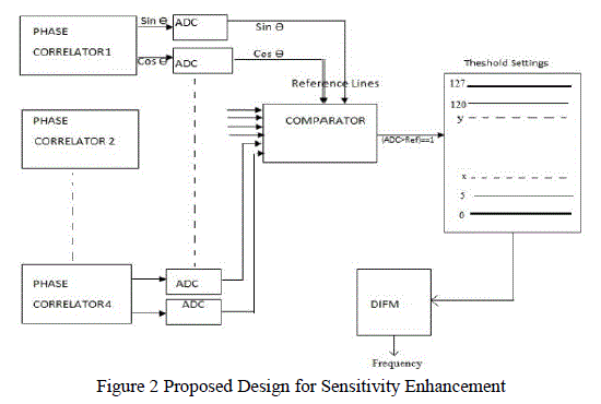
| Phase correlator is fed with one undelayed signal along with its delayed signal. Each phase correlator produces one sine and cosine wave using the I & Q hybrid. The outputs of Phase correlator are sine Ãâ ß and cosine Ãâò. These signals are passed to different ADCâÃâ¬ÃŸs i.e. one ADC for each signal. Here at this stage a method called unwrapping is done to resolve the phase difference. That is in order to avoid over lapping of signals at same phase. The outputs of ADCâÃâ¬ÃŸs are sent to comparator. The comparator is fed with the reference line. Here we consider the shorter delay lines as the reference signal, as the shortest delay line is used to resolve the ambiguities. The output of comparator is high if the output of ADC is greater than the reference line. The ADC output is considered only if the signal received is higher than the reference line else it is discarded. The signal which is higher than reference line is sent for signal conditioning. Then the signal conditioned output is sent into FPGA. |
| Our main concept is to enhance sensitivity. So we are introducing a new concept called setting of 2nd threshold. The threshold is set to the received signal. The aim of this method is to eliminate the noise present at the lower and higher bits of the incoming signal to FPGA. i.e 0 to „xâÃâ¬ÃŸ at lower bits and 127 to „yâÃâ¬ÃŸ at higher bits (as shown in figure 2). That is the signal is sent into DIFM if it lies between the parameters „xâÃâ¬ÃŸ and „yâÃâ¬ÃŸ. The DIFM is used to measure the received signal. Hence in this way we are enhancing the sensitivity of the system. |
 |
| The objective of the paper is to enhance the sensitivity of the system. The technique used here is noise suppression. This technique is analyzed in MATLAB and implemented on FPGA based digital board. The result obtained is approximate to the received frequency. The RMS error is 1Mhz and the Maximum error is +/- 3Mhz. |
 |
VI. CONCLUSION AND FUTURE SCOPE |
| In the proposed approach the receiver sensitivity enhancement is done by using quad phase correlator instead of a single phase correlater which was used in existing regular DIFM. The quad phase correlator is the combination of four correlators. As we are using 4 corelators, they suppress the effects of noise more efficiently and improve frequency accuracy. This approach can be extended for EW Direction Finding measurement which will be taken up as future activity. It is also seen that sorting of simultaneous signals is difficult so there is possibility to work on the improvement of sorting of simultaneous signals. |
VI. ACKNOWLEDGEMENT |
| My sincere thanks to my internal guide Mr. Tavanam Venkata Rao, Associate Professor, ECE, SNIST for the encouragement and guidance provided. I am also grateful to Dr. Venumadhao Rao, Head Of the Department, ECE, SNIST for his continuous support and valuable guidance. I am also thankful to Dr. Narseema Rao Reddy, Director, SNIST for his valuable guidance. |
References |
|