ISSN ONLINE(2319-8753)PRINT(2347-6710)
ISSN ONLINE(2319-8753)PRINT(2347-6710)
G. Pandian1, S. Rama Reddy2
|
| Related article at Pubmed, Scholar Google |
Visit for more related articles at International Journal of Innovative Research in Science, Engineering and Technology
This paper presents Simulation of three phase PWM Inverter fed Induction Motor Drive using Pspice. The proposed induction motor drive model employs only seven switches and incorporates an active current shaping feature. The boost converter at the input can give the required voltage at the input of inverter. The boost converter also improves the power factor. The drive works satisfactorily at low input voltage since the boost converter maintains required voltage.
Keywords |
| Diode, PWM, voltage vector, inverter, induction motor. |
I. INTRODUCTION |
| Pulse Width Modulated (PWM) inverter systems are used in a wide variety of applications as a front-end powerconditioning unit in Electric drives, Uninterruptible power supplies, High Voltage DC transmission, Active power filters, reactive power compensators in power systems, Electric vehicles, Alternate energy systems and Industrial processes. The inverters realize dc-to-ac power conversion and in the most commonly used voltage source inverter configuration. The dc-input voltage can be obtained from a diode rectifier or from another dc source such as a battery [1]. A typical voltage source PWM inverter system consists of rectifier, DC-link, PWM inverter along with associated control circuit and the load. Most modern voltage source inverters are controlled using a wide variety of pulse width modulation schemes, to obtain output ac voltages of the desired magnitude and frequency shaped as closely as possible to a since wave. Analysis of PWM inverter system is required to determine the input-output characteristics for an application specific design, which is used in the development and implementation of the appropriate control algorithm [2]. In addition to time domain analysis, harmonic assessment is an integral part of analysis and simulation of any power conversion system. |
II. THREE PHASE PWM INVERTER |
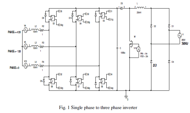
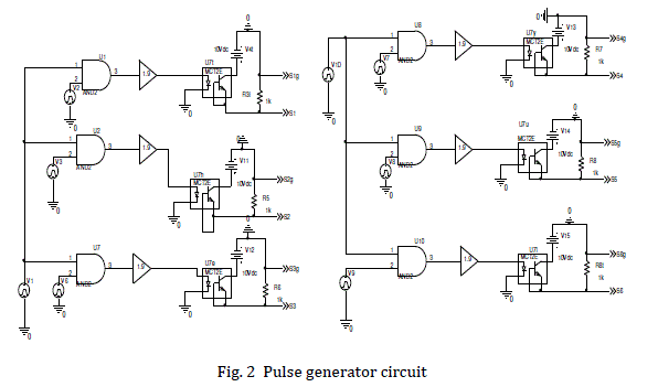
| The three-phase PWM inverter is the dc-ac converter as shown in figure 1. The PWM inverter is to generate nearly sinusoidal current which it can be controlled. The voltage and current are controlled with 120o different in each phase. The controlling signals of three-phase PWM inverters have many pattern controls. The operations three-phase inverter can be defined in eight modes [5] which shows status of each switch in each operations mode. From operations mode, the current can not flow to load in mode 0 and 7 while current can flow to load in mode 1 to 6. Then, it can draw two equivalent circuits for operations mode which mode 1 operation is the same as of those 2 and 4 and mode 3 is the same as 5 and 6. Whether during rectification or inversion, sinusoidal current shaping can be reduced to a voltage control in which the controlled voltage source is connected to an ac source through an inductance. The pulse generator for single phase to three phase and three phase to three phase inverter fed drive system is shown in figure 2. |
| In inverter operation, the necessary phase-leg-short is naturally realized through anti-parallel diodes in the three-phase bridge. Accordingly, the same gate pulses as in the conventional VSI can be applied. On the other hand, the switch on the dc link must actively operate. The operation of PWM inverter can generate noises into the system in both of conducted and radiated EMI. The conducted EMI measurement which is succeed by Line Impedance Stabilization Network, from the investigation of input voltage waveform of the inverter, the waveform consists of fundamental signal and high frequency signals. The high frequency signals or ringing signal are undesigning signals which call noises. The ringing signals are detected by Line Impedance Stabilization Network. Then the ringing signals are noises, which are occurred by the operating of the switching devices of PWM inverter, during turn-on or turn-off condition [6]. |
 |
III. VOLTAGE SOURCE INVERTER FED INDUCTION MOTOR |
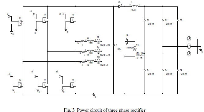
| The circuit model of three phase rectifier with boost converter and three-phase inverter system is shown in Figure 3. The output is connected to the three phase stator of star connected induction motor. The power devices are assumed to be ideal, when they are conducting, the voltage across them is zero, they present an open circuit in their blocking mode. The phase voltages are derived from the line voltages in the following manner by assuming a balanced three-phase system [9]. |
| The line voltages in terms of the phase voltages in a three-phase system with phase sequence abc are |
 |
 |
| Irrespective of the control strategies employed in the induction motor drive, the input voltages are periodic in steady state. Hence, direct steady-state performance evaluation is possible by matching boundary conditions. PWM voltage inputs are considered for steady-state performance evaluation of the induction motor drive system. The PWM can be generated in any number of ways, sine-triangle, trapezoidal-triangle, space vector, sampled asymmetric method modulation strategies, etc. Because of their symmetry for either half-wave or full-wave, the boundary-matching technique is ideal for evaluating the steady-state current vector directly, without going through the dynamic simulation from start-up. |
 |
IV. SIMULATION RESULTS |
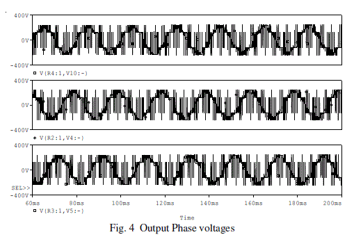
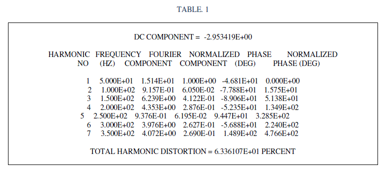
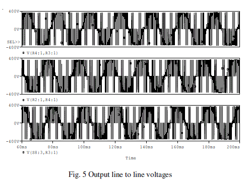
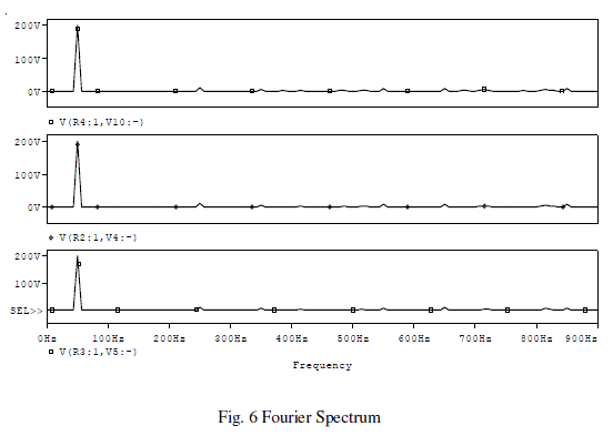
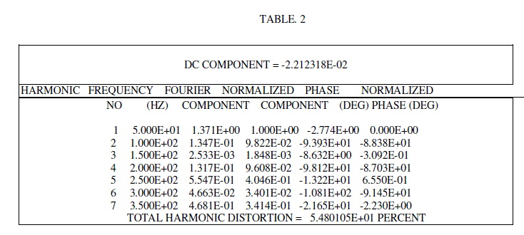
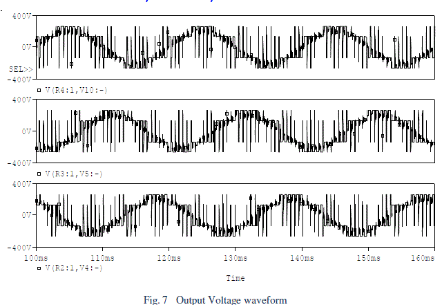
| In three phase inverter fed drive circuit, the low voltage AC is converted into DC using a diode rectifier. It is boosted to the required value using the boost converter. DC is converted to variable voltage variable frequency AC using three phase PWM inverter. The output of PWM inverter is fed to the three phase induction motor. The phase voltage and line to line voltage are shown in figures 4 & 5 respectively. The fourier spectrum for the single phase to three phase inverter is shown in figure 6 and the fourier data is furnished in the table-1. The phase voltage waveforms for three phase to three phase inverter system are shown in figures 7 and the current waveforms are shown in figure 8. The fourier spectrum for this inverter system is shown in figure 9 and the fourier data is given in the table-2. |
 |
 |
 |
 |
 |
 |
V. EXPERIMENTAL RESULTS |
| Microcontroller based voltage source inverter fed induction motor system is fabricated and tested. The control circuit is shown in Figure 10. The top view of the hardware is shown in Figure 11. The oscillogram of driving pulses from the micro controller are shown in Figure 12.The oscillogram of phase voltage is shown in Figure 13. The Atmel microcontroller 89C2051 is used to generate the pulses. The microcontroller operates at a clock frequency of 12 MHZ. The pulses produced by the microcontroller are amplified using the driver IC IR 2110. The driver ICs amplify the gate pulses to the required level. |
 |
 |
VI. CONCLUSION |
| The circuit models for single phase to three phase inverter system and three phase to three phase inverter system were developed. The analysis of voltage source inverter fed induction motor drive was presented. The three phase PWM inverter fed induction motor drive is simulated using the circuit model developed. The simulation and experimental results for single phase to three phase inverter system and three phase to three phase inverter system are presented. The frequency spectrum for these cases is also presented. From the simulation studies it is observed that the harmonic distortion was lesser (5%) in three phase to three phase inverter system compared to the harmonic distortion with single phase to three phase inverter system (6.3%). The present work has suggested boost converter for inverter fed induction motor drive system to tackle the low input voltage problem. A 1KW inverter fed induction motor system is fabricated and tested. The experimental results coincide with the simulation results. |
References |
|