ISSN ONLINE(2319-8753)PRINT(2347-6710)
ISSN ONLINE(2319-8753)PRINT(2347-6710)
Ms. K. Suganya1 and Mr. S. Rameshkumar2
|
| Related article at Pubmed, Scholar Google |
Visit for more related articles at International Journal of Innovative Research in Science, Engineering and Technology
Brushless DC (BLDC) motor drives are becoming more popular in industrial and traction applications. The control of BLDC motor in four quadrants is very vital. This paper deals with the fuzzy logic control of three phase BLDC motor. Without any loss of power the motor can be controlled in all the four quadrants. During regenerative braking period energy is conserved. The calculation capability of digital signal processor and controlling capability of fuzzy logic controller is used to achieve a precise control.
Index terms |
| BLDC motor. dsPIC, fuzzy logic control, four quadrants, regenerative braking. |
INTRODUCTION |
| A typical brushless motor has permanent magnets which rotate and a fixed armature, eliminating problems associated with connecting current to the moving armature. An electronic controller replaces the brush/commutation assembly of the brushed DC motor, which continually switches the phase to the windings to keep the motor turning. The controller performs similar timed power distribution by using a solid-state circuit rather than the brush/commutation system. The motor has less inertia, therefore easier to start and stop. Bldc motors are potentially cleaner and faster, more efficient, less noisy and more reliable. BLDC motors are a type of synchronous motor. This means the magnetic field generated by the stator and the magnetic field generated by the rotor rotates at the same frequency. BLDC motors do not experience the “slip” that is normally seen in induction motors. BLDC motors come in single-phase, 2- phase and 3-phase configurations. Corresponding to its type, the stator has the same number of windings. Out of these,3-phase motors are the most popular and widely used. This application note focuses on 3-phase motors. |
| BLDC motors are used in Automotive, Aerospace, Consumer, Medical, Industrial automation equipments and instrumentation. This paper is organized as follows: section II describes the four quadrant operation of three phase BLDC motor, its features; the controller is explained in Section III. The simulink model is reviewed in section IV. In Section V, the simulation results of four quadrant operation of the BLDC motor with the results are presented.In section VI conclusion of four quadrant is presented. |
 |
FOUR QUADRANT OPERATION OF BLDC MOTOR |
| A.HALL SENSOR |
| Unlike a brushed DC motor, the commutation of a BLDC motor is controlled electronically. To rotate the BLDC motor, the stator windings should be energized in a sequence. It is important to know the rotor position in order to understand which winding will be energized following the energizing sequence. Rotor position is sensed using Hall effect sensors embedded into the stator. Most BLDC motors have three Hall sensors embedded into the stator on the non-driving end of the motor. Whenever the rotor magnetic poles pass near the Hall sensors, they give a high or low signal, indicating the N or S pole is passing near the sensors. Based on the combination of these three Hall sensor signals, the exact sequence of commutation can be determined. |
| Hall sensors are embedded into the stationary part of the motor. Embedding the Hall sensors into the stator is a complex process because any misalignment in these Hall sensors, with respect to the rotor magnets, will generate an error in determination of the rotor position.To simplify the process of mounting the Hall sensors onto the stator, some motors may have the Hall sensor magnets on the rotor, in addition to the main rotor magnets. These are a scaled down replica version of the rotor. Therefore, whenever the rotor rotates, the Hall sensor magnets give the same effect as the main magnets.The Hall sensors are normally mounted on a PC board and fixed to the enclosure cap on the non-driving end. This enables users to adjust the complete assembly of Hall sensors, to align with the rotor magnets, in order to achieve the best performance. Based on the physical position of the Hall sensors, there are two versions of output. The Hall sensors may be at 60° or 120° phase shift to each other. Based on this, the motor manufacturer defines the commutation sequence, which should be followed when controlling the motor. |
| B.FOUR QUADRANT OPERATION |
| There are four possible modes of operation which is depicted in fig.2 |
| When the BLDC motor is operated in the first and third quadrant which is forward motoring and reverse motoring modes, the supplied voltage is greater than the back emf. When the motor operated in second and fourth quadrant which are forward braking and reverse braking modes, the value of back emf generated by the motor should be greater than the supplied voltage. The direction of current flow is reversed. The BLDC motor is initially made to rotate in clockwise direction, but when the speed reversal command is obtained, the control goes into the clockwise regeneration mode, which brings the rotor to the standstill position. Instead of waiting for the absolute standstill position, continuous energization of the main phase is attempted. This rapidly slows down the rotor to a standstill position. Therefore, there is the necessity for determining the instant when the rotor of the machine is ideally positioned for reversal. |
PROPOSED CONTROLLER |
| A.DSP CONTROLLER |
| The controller has a modified Harvard architecture, with a 16×16 bit register working array. It has two 40 bit wide accumulators. All the DSP instructions are performed in a single cycle. The three external interrupt sources, with eight user selectable priority levels for each interrupt sources. The reference speed and the required duty cycle can be fed to the controller. The closed loop control is achieved using fuzzy logic controller |
 |
| B.FUZZY LOGIC CONTROLLER |
| The disadvantage of PI controller is its inability to react to abrupt changes in the error signal, ε, because it is only capable of determining the instantaneous value of the error signal without considering the change of the rise and fall of the error, which in mathematical terms is the derivative of the error denoted as Δε. To solve this problem, Fuzzy logic control is used. Fuzzy logic is a form of many-valued logic; it deals with reasoning that is approximate rather than fixed and exact. Compared to traditional binary sets (where variables may take on true or false values) fuzzy logic variables may have a truth value that ranges in degree between 0 and 1. Fuzzy logic has been extended to handle the concept of partial truth, where the truth value may range between completely true and completely false. Furthermore, when linguistic variables are used, these degrees may be managed by specific functions. Irrationality can be described in terms of what is known as the fuzzy. |
 |
| The determination of the output control signal, is done in an inference engine with a rule base having if-then rules in the form of “IF ε is…..AND Δε is…..THEN output is……” With the rule base the value of output is changed according to the value of error signal, the rate of change of error. The structure and determination of rule base is done using trial and error method. |
| C. PWM MODULE |
| The PWM module simplifies the task of generating multiple synchronized Pulse width modulation(PWM)outputs. It has six PWM I/O pins with three duty cycle generators. The three PWM duty cycle registers are double buffered to allow glitch less updates of PWM outputs. For each duty cycle, there is a duty cycle register that will be accessible by the user while the second duty cycle registers holds the actual compared value used in the present PWM period. The output compare module generates an interrupt to trigger the relay circuit during regenerative mode. |
SIMULINK MODEL |
| The simulink model of the BLDC motor. The closed loop controller for a three phase sensor less BLDC motor is modified using MATLAB/Simulink is shown in fig.14 |
| The fuzzy controller receives the signal as its input, converts it to appropriate voltage signls.The gate signals are generated by comparing actual speed with reference speed. Thus a closed loop speed control is achieved with the help of fuzzy controller. The simulation results are shown in fig. indicates that, when a negative torque is applied at a time 0.6s,there is a peak overshoot in the actual speed, which means it aids the motor to run. At other times the speed is stabilized with reference speed. The reference speed is 400rpm. |
 |
SIMULATION RESULTS |
| In Figure 7, the waveform shows that the battery starts energizing from the instant the speed reversal command is received. The oscillations die out gradually as the motor changes its direction of rotation. The Pulse Width Modulation (PWM) pulses applied to the inverter circuit at the appropriate time to trigger the appropriate switches are the control signals to the circuit. It depicts that the motor is running in the forward direction, after a time interval brake is applied, the motor stops decelerating at this point the battery starts charging. The battery is energized during the regenerative period. |
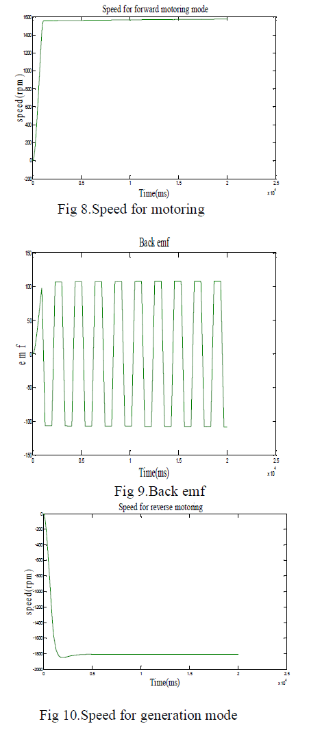
| Figure 8 shows the speed for the forward motoring operation of three phase BLDC motor. When BLDC motor is operating in the first and third quadrant, the supplied voltage is greater than the back emf which is forward motoring and reverse motoring modes respectively, but the direction of current flow differs.In figure 9 the back emf is shown. In the figure 10 the speed for generation mode is shown. |
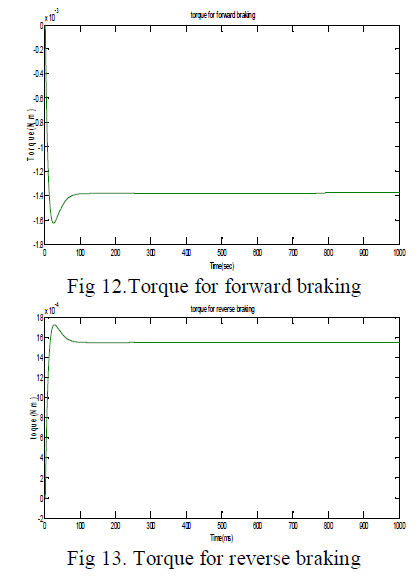
| In Fig 11shows the current for reverse braking and Fig 12 shows the torque for forward motoring. |
 |
 |
CONCLUSION |
| In this paper a control scheme is proposed for sensor less BLDC motor to change the direction from CW to CCW and the speed control is achieved. In this paper fuzzy logic control is proposed to control the speed. The speed is controlled is shown in the waveforms. It is possible to control the speed and maintain the torque constant. The simulation results are shown. The advantages of this proposed method are: simple hardware circuit, excellent speed control, smooth transition between the quadrants and efficient conservation of energy. |
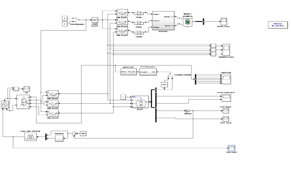 |
| Figure 14: simulink model |
References |
|