ISSN ONLINE(2319-8753)PRINT(2347-6710)
ISSN ONLINE(2319-8753)PRINT(2347-6710)
A.Karthik 1, R.Krishnaraj1, Nunnakarthik1, R.Kumaresan 2, S.Karthik 2, R.Murali 2
|
| Related article at Pubmed, Scholar Google |
Visit for more related articles at International Journal of Innovative Research in Science, Engineering and Technology
Under conventionally controlled drilling machine the depth controlled cannot be made possible. Due to over drilling the job gets failed. While drilling we cannot measure the drilling depth during drilling process. Hence the semiautomatic drilling machine will automatically control the depth of the job and it of safer mode. In some cases due to over drilling the work bench will gets destroyed or the tool will be damaged. Hence for these conditions our project work had been taken up to get through the new technologies. This made the drilling machine easier. This semiautomatic drilling machine is very well used in mechanical workshops and it made the work easier. It consumes less time and the finishing process will be quite easier, while compared to the conventional drilling machine.
Keywords |
| Depth controlled mechanism, Portable hand drilling machine, Limit switch, and Hydro pneumatic cylinders. |
INTRODUCTION |
| With the resent development of technology, higher precision and speed are required for drilling machine. Therefore, improved performance of drilling machine should be developed to satisfy the demands of the times. In order to meet the machining requirements for complex and precise products, the PLC machine tool has been developed into a precision machine for drilling machine. Therefore, this mechanism retains the advantages of the parallel machine tool and the continuous-path traceability of the X–Platform, and forms a new type of single axis machine[2] .Most industrial robots have open kinematic chains and serially connected links. A hydraulic pneumatic booster has the advantages of a high stiffness, high precision, low inertia, and simple mechanism. Shortcoming of a small operating space can be overcome to increase the sensitivity, in order to simplify the complexity of the drilling machine operation Conventionally drilling machine like hand drilling machine, power feed drilling machine, etc. These machines are available everywhere at any rates. Often these machines are used for drilling a hole through the job. It require human source at any time but in some automatic drilling machine it requires less skilled labours. In simple drilling machine the depth controlled cannot be estimated properly[5].Hence the simple drilling machine consumes more time for a single job but this semi-automatic drilling machine drilling operations can be done at less time and it is time saving and while comparing both simple drilling machine and semi-automatic drilling machine, the time taken for one job in simple drilling machine, the semi-automatic drilling machine will complete three jobs at the same time. Hence it is very much used in mechanical workshops for time consuming progress. The drilling depth was quite accurate and smoother. |
| Feed is controlled automatically with hydro-pneumatic cylinder. Portable hand drilling machine held in horizontal platform with a clamping attachment. It is fitted to pistons of hydro-pneumatic cylinders. In hydro-pneumatic cylinders the oil cylinder output is connected with PVC pipe lines. The drilling depth is controlled by limit switch. If the limit switch is pressed the drilling machine will stop and it returns back. PlC controlled solenoid valve are connected to output. The signal from the switch is fed to the electrically controlled PLC.[7] |
II. BLOCK DIAGRAM AND ITS DESCRIPTION |
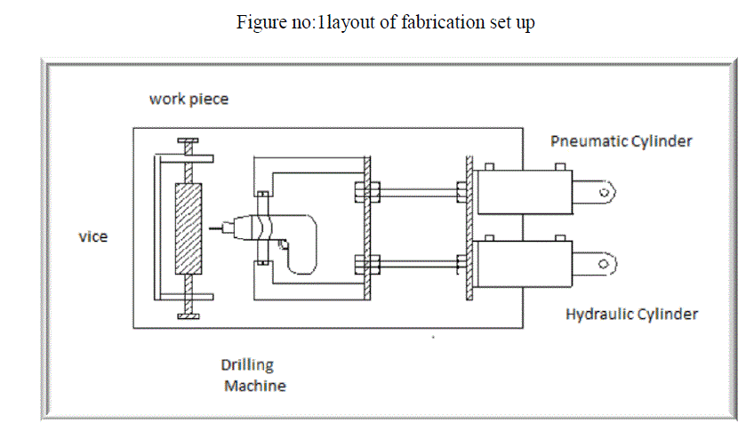
| Design of single axis semi-automatic increase the Reliability by optimize cushion effect of drilling machine and application flexibility is increased more Compare to the standard drilling machine. Semi-automatic drilling machine with the PLC control: In the past, all drilling operation associated with vibration which results in the noise environment and the worker get fatigue. Drilling machine with the PLC control to increase reproducibility with improved accuracy and the quality of drilling process is optimized. The practical difficulties of using PLC limit its application. The ongoing research being conducted into the use of PLC control in drilling machine reveals that they have great potential leads to decreasing the vibration and controlling speed of drilling machine with optimum cushioning effect. The design and implementation of a on PLC control system in drilling machine, involve software for PLC and hardware related to the programs. Satisfactory combination ladder program code into PLC system that fulfil the requirements of control of drilling machine with PID controller[8].Optimum level Hardware design for the drilling machine is followed and Software of PLC system encoded.The main concept of this special drilling machine is to reduce the man power and for time saving and for better finish. These kinds of special drilling machines are very much used in mechanical workshops for specific job applications. It consists of both pneumatic and hydraulic cylinders. The hydraulic cylinder is used for cushioning process because the pneumatic cylinder will moves faster, if it moves faster than the piston of the cylinder will gets damaged and the drilling machine will moves suddenly, if it moves faster than the drill bit will damage. The output of the hydraulic cylinder is again connected to the input of the same cylinder using a PVC pipeline. The input and output of the pneumatic cylinder is connected to the solenoid valve where the compressed air will be regulated from the compressor. Then drilling machine is fitted with a rectangular movable frame. The frame is then connected to the piston of the two cylinders. The drilling depth of the drilling machine is then controlled by a limit switch. The limit switch is attached to the rectangular frame. The limit switch is movable. It can be adjusted at any height. At the base there was a workbench where the work piece is placed for drilling. |
 |
III. WORKING |
| The rate of drilling depends on Nature of the work piece, Pressure exerted by drilling bits and rods, the rpm of the tool bit and the type of drilling bit used in drilling process. These are thread connected and transmit torque and feed pressure to the drilling bit or drilling tool, which is attached at the end of column of the drill rods. Rotation of the drill rods is through gearing driven by a prime mover at the surface. The drill bit attacks the work piece with energy supplied to it by a rotating drill rod. As the rods rotate, the drilling tool/bit breaks the work piece and PLC senses the back pressure caused by effect drilling increase cushioning effect by proper maintenance hydraulic pneumatic booster. The bit moves forward meanwhile vibration reduced in drilling machine. If the power supply is supplied and the compressed is allowed to flow through the solenoid valve it will regulate the air flow and the pneumatic cylinder as well as the drilling machine starts works and the work piece is kept on the workbench. The limit switch is adjusted then the drilling machine will moves down and it will drills the work piece at the controllable depth. After it reaches the certain depth the drilling machine will stop drilling and it returns back to its original height. This process is repeated for each work piece. And it is used for mass production. |
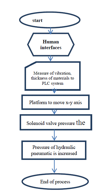
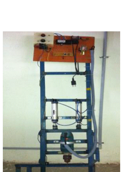
IV. PHOTOGRAPH OF PROTOTYPE & BLOCK DIAGRAM OF PLC SYSTEM. |
 |
 |
V. CONCLUSION |
| In this paper, hydraulic pneumatic booster used to reduce the vibration of drilling machine was integrated into an XY motion platform to form a reconfigurable single -axis machine. We successfully determined the effects of the drive shafts of the platform on the platform attitude. The measured results were used as reference data to adjust the flatness of the movable plate by PLC system. Then, the platform attitudes were measured. After determining the depth of work piece and the deviations of the centers of the fixed plate and movable plate, and the height of the drive shafts, were revised, this successfully reduced the error and significantly improved the precision of the platform attitude. PLC was used to measure the work pieces to verify the revision results of the mechanism. We determined the precision of the mechanism based on the measured results. Therefore, the drilling depth accurately and smoother within a short span of time.Scope of the present work is about using PLC in drilling machine leads to Optimization process and drilling is smooth and less noise when compared to other machine. The operator feels more combatable with PLC |
References |
|