ISSN ONLINE(2319-8753)PRINT(2347-6710)
ISSN ONLINE(2319-8753)PRINT(2347-6710)
| Vijayanandh.A1, Santhoshkumar .T2 Department of Electrical and Electronics Engineering, Valliammai Engineering College, Chennai, India |
| Related article at Pubmed, Scholar Google |
Visit for more related articles at International Journal of Innovative Research in Science, Engineering and Technology
This project presents the analyzed results of an integrated seashore wave and offshore wind farm fed to a power grid through a unified power flow controller (UPFC) to simultaneously achieve power-fluctuation mitigation and stability improvement. A PID controller of the proposed UPFC is designed by using modal control theory to render adequate damping characteristics to the studied system. A frequency-domain approach based on a linearized system model using eigenvalue analysis and a time-domain scheme based on a nonlinear system model subject to disturbance conditions are systematically carried out. The inherent power fluctuations injected to the power grid can also be effectively mitigated by the proposed control scheme. The simulation of the proposed model was carried out using MATLAB/PSAT and the effective performance was analyzed.
Keywords |
| —Damping controller, offshore wind farm (OWF), seashore wave farm (SWF), stability, unified power flow controller (UPFC). |
INTRODUCTION |
| Since oceans cover more than 70% surface of the earth, the wind energy above the sea surface and the oceanic wave energy near coast can be simultaneously captured to generate large electric power fed to power grid. An offshore wind farm (OWF) combined with a seashore wave farm (SWF) can be effectively developed in different countries with coast. The connection point of the generated power of both OWF and SWF may be near coast, and the reason for having these two different energy forms close to each other is driven by geographical conditions, infrastructure, and planning permission. Both ocean energy and wind energy have been effectively combined together in European countries [1], [2]. Seashore wave power generation systems combined with offshore wind turbine generators have the potential for large electric energy production in the near future. For the study of characteristics of a commercial onshore wind farm, the authors employed the field measured data of one of the commercial wind farms in Taiwan to establish a detailed wind-farm system model for simulations [3], [4]. This wind farm has 23 wind DFIGs fed to the 161-kV extra-high-voltage bus of Taiwan Power System through a 23/161-kV main transformer and six 23-kV feeders with current-limit reactors. Since the model establishment and stability analysis of grid-connected wave energy conversion system of 100 kW using an IG driven by a Wells turbine was performed in [5], a SWF model can be obtained by aggregating several IG-based grid-connected wave energy conversion systems. This paper proposes a unified power flow controller (UPFC) as a control scheme to achieve power flow control of the hybrid DFIG-based OWF and IG-based SWF. |
| The major contribution of this project is that large power fluctuations injected to the power grid can be effectively mitigated by the proposed UPFC joined with the designed damping controller. The damping controller of the proposed UPFC is designed by using a systematic approach based on modal control theory to achieve simultaneous power-flow control and stability improvement of the studied integrated OWF and SWF system under wind-speed changes. |
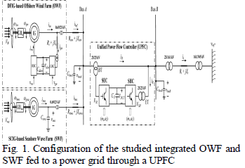 |
| Fig. 1 shows the configuration of the studied integrated DFIG-based OWF of 100 MW and SCIG-based SWF of 60 MW fed to a power grid through the proposed 160- MW UPFC. The OWF is represented by an equivalent aggregated DFIG driven by an equivalent aggregated variable-speed WT through an equivalent aggregated gearbox GBw [17]. The SWF is represented by an equivalent aggregated SCIG driven by an equivalent aggregated variable-speed Wells turbine through an equivalent aggregated gearbox GBWa [17]. The OWF and the SWF are connected to Bus A that is fed to the 161- kV onshore power grid through a 23/23-kV UPFC, a 23/161-kV offshore step-up transformer, and a 161-kV undersea cable. The employed mathematical models of the studied system are described in [1]. |
UPFC MODEL |
| The UPFC basic control design consists of four separate control loops grouped into a series control scheme, whose objective is to control real and reactive power flow on the line, and a shunt control scheme, whose objective is the control of the sending bus voltage magnitude and the DC voltage magnitude. The q –d axis voltage equations of the SHC can be described, respectively, by |
| while the q –d -axis voltage equations of the SEC can be depicted, respectively, by |
 |
| The active and reactive power of the SHC can be written respectively, by |
| The active and reactive power of the SEC can be written respectively, by |
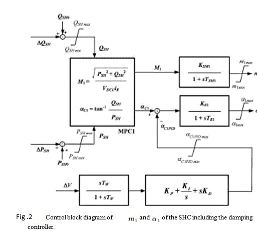
| above, fig 2 m1 and α1 of the SHC can be obtained from M1 and αC1 through a first order lag , respectively, while M1 and αC1 are calculated PSH and QSE using calculator MPC1. |
 |
 |
| above, m2 and α2 of the SEC can be obtained from M2 and αC2 through a first order lag , respectively, while M2 and αC2 are calculated PSE and QSE using calculator MPC2. |
 |
 |
| III. DESIGN OF A DAMPING CONTROLLER FOR UPFC USING MODAL CONTROL THEORY |
| This section employs a unified approach based on modal control theory to design a PID damping controller for tuning the phase angle α1 of the SHC of the proposed UPFC shown in Fig. 5 to improve dynamic stability of the studied integrated OWF and SWF system. The nonlinear system equations developed in Section II are first linearized around a nominal operating point to obtain a set of linearized system equations in matrix form of [25] |
 |
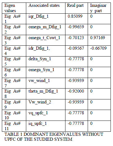
| where X is the state vector, Y is the output vector, U is the external or compensated input vector, W is the disturbance input vector while A B C D and are all constant matrices of appropriate dimensions. To design a damping controller for the proposed UPFC, W in (1) and U in (2) are neglected by setting D = V =0.The following analyzed results can be obtained by examining the modes listed in Table I |
| 1) the modes of the wind DFIG, the modes of the wave SCIG, and the electrical modes of the studied system are almost fixed on the complex plane |
| 2)both and are located close to the imaginary axis of the complex plane and the damping of both modes can be simultaneously improved by properly adding the designed PID damping controller to the control block diagram of the SHC; and 3) all system eigenvalues are located on the left half of the complex plane under a fixed wind speed and a fixed axial speed..The control block diagram of the phase angle of the state vector X can be partitioned into five sub state vectors as X=[ XDFIG-OWF, XSCIGSWF, XMECH, XLC, XUPFC]T where XDFIG-OWF, XSCIGSWF, XMECH, XLC, XUPFC are referred to the system state vectors of the wind DFIG of the OWF, the wave SCIG of the SWF, the mechanical systems of both WT and Wells turbine, the electrical system including the AC buses and transmission lines, and the UPFC, respectively Vw seldom reaches VWRATED (15 m/s) and seldom operates above its highest value of 7 m/s, VW of 10 m/s and VA of 6 m/s are properly selected as the nominal operating points for designing the PID damping controller at the SHC of the UPFC. |
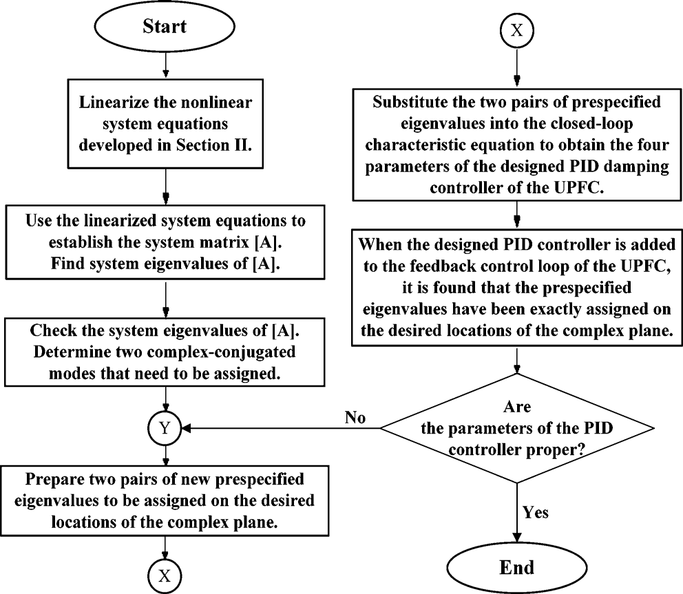 |
| Fig.3. Basic flowchart of designing the PID damping controller for the pro-posed UPFC using pole-placement scheme |
 |
| IV. SIMULATION STUDY |
| In the test system, a DFIG and SCIG is connected to step down transformer of (161/23KV).SCIG(60MW)and DFIG(100MW) are connected parellel with 23 KV grid. Generally DFIG and SCIG are used to generate power with wind farm and wave farm. The voltage and current at the grid side contain variation in waveforms. These variations are caused by change in generator output voltage . This problem will rectified using UPFC. |
| The system eigenvalues of the studied integrated OWF and SWF without UPFC joined the designed PID controller are listed in the column of Table I. It can be clearly observed that both and have been exactly positioned on the desired locations on the complex plane. Fig. 3 shows the basic flowchart of designing the PID controller for the proposed UPFC using poleplacement scheme.eigen-Value analysis is carried out for the test system without UPFC and the results are presented. |
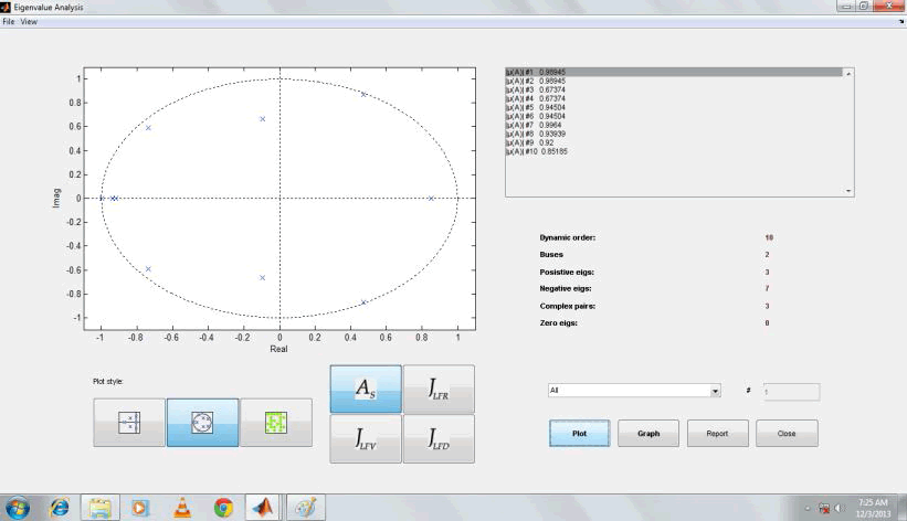 |
| Fig 5.Z domain map of eigen values with UPFC |
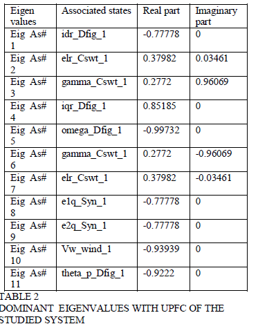
| From, the comparative analysis of eigen value before and after the placement of UPFC by using PSAT software. The system eigenvalues of the studied integrated OWF and SWF without UPFC joined the designed PID controller of Z domain of eigen values by PSAT TOOLS. Eigen-Value analysis is carried out for the test system without UPFC and the results are presented. PID controller for the proposed UPFC using pole-placement scheme eigen-Value analysis is carried out for the test system without UPFC and the results are presented. |
| The dominant system eigenvalues of the studied integrated OWF and SWF with UPFC joined with the designed PID controller are listed in the column of Table 2. It can be clearly observed that both and have been exactly positioned on the desired locations on the complex plane. Fig. 3 shows the basic flowchart of designing the PID controller for the proposed UPFC using pole-placement scheme.eigen-Value analysis is carried out for the test system with UPFC and the results are presented. |
 |
| The response of the voltage magnitude of Bus A and Bus B changes can be reduced by addition of UPFC to the system. UPFC is used in the system for maintain the stability of the grid voltage and control the both real and reactive power. |
 |
CONCLUSION |
| This paper has presented stability improvement and power flow control of a grid-connected hybrid system containing a large-scale 60-MW seashore wave farm (SWF) and 100-MW offshore wind farm (OWF) using a 160-MW unified power flow controller (UPFC). The dqaxis equivalent- circuit model has been employed to establish the models of the SWF, the OWF. It is found that the system remained marginally stable with and without UPFC. The damping controller of the shunt converter of the UPFC has been designed by using modal control theory. The effectiveness of the proposed UPFC has been evaluated by a systematic approach using a frequency-domain approach based on eigenvalue analysis under various wind speeds |
References |
|