ISSN ONLINE(2319-8753)PRINT(2347-6710)
ISSN ONLINE(2319-8753)PRINT(2347-6710)
Mohammed Imran1, Shabbir Ahmed.R.M2, Dr. Mohamed Haneef3
|
| Related article at Pubmed, Scholar Google |
Visit for more related articles at International Journal of Innovative Research in Science, Engineering and Technology
Stress analysis plays very important role in finding structural safety and integrity of assemblies. The prior estimation of stress helps in finding suitable material and geometrical dimensions. Even optimisation of dimensions are possible with stress estimates along with factor of safety calculations. Factor of safety indicates the safety margin of the designed structure which indicates how much the structure is overdesigned and how safe the components are. Landing gear is the most important component in the aircraft system and it is observed from the literature that majority failures of aircraft structure takes place due to malfunction of landing gear. In the present work, a landing gear is cad designed and analysed for structural safety for static and spectrum loads. The maximum possible loads which are given as design loads are applied through RBE3 connection at the axle end spreading to wheel base. Initially present material Aluminium is used to check the strength of the landing gear for self weight, static loads, Modal Conditions and shock spectrum loads as per mil standards. The results shows higher stresses and deflections with aluminium material.
Keywords |
| Landing Gear Optimization, Structural Safety, Aluminium Materials, Static and Dynamic behaviour |
INTRODUCTION |
| A complete airplane structure is manufactured from many parts. An aircraft is a complex structure, but a very efficient man-made flying machine. Despite this some main components became permanent in every aircraft dressing. Most airplane structures include a fuselage, wings, an empennage, landing gear, and a power plant and propulsion devices. There are many other parts as well. Each component has one or more specific functions and must be designed to ensure that it can carry out these functions safely. Any small failure of any of these components may lead to a catastrophic disaster causing huge destruction of lives and property. If a part fails, it doesn’t necessarily result in failure of the whole aircraft. It is still possible for the aircraft to glide over to a safe landing place only if the aerodynamic shape is retainedstructural integrity is achieved. |
| The landing gear is the principle support of the airplane when parked, taxiing, taking off, or when landing. The most common type of landing gear consists of wheels, but airplanes can also be equipped with floats for water operations, or skis for landing on snow. Landing gear is essentially one dimension structure under heavy compressive loads. Drag load and side load do act on landing gear however. Landing gears enable the aircraft to land and takeoff from the ground. A number of loads curve are specified in a FAR rules books for which landing gear for a given type of aircraft is to be designed. Some of these are (1) Level landing, (2) One wheel landing, (3) Level landing with spring back, etc. The primary role of a landing gear is to enable the ground operation of the air craft. During landing it is designed to absorb the landing impact energy such that the loads transmitted to the air frames are minimised. Apart from static strength, energy absorption is an important design criterion. For small aircraft a lip spring type of landing gear is normally sufficient to absorb the impact energy. These are retractable however for heavier aircraft, oleo pneumatic landing gear strut are the normal choice. These are retractable too. Landing gears are normally are generally “safe life” components and are replace many times during the service life of the aircraft. |
| Traditional metallic materials used in aircraft structures are Aluminium, Titanium and steel alloys. Selection of aircraft materials depends on any considerations, which can in general be categorized as cost and structural performance. Cost includes initial material cost, manufacturing cost and maintenance cost. The key material properties that are pertinent to maintenance cost and structural performance are Seldom is a single material able to deliver all desired properties in all components of the aircraft structure |
| Aluminum alloys |
| Aluminum alloys have played a dominant role in aircraft structures for many decades. They offer good mechanical properties with low weight. Among the aluminum alloys, the 2024 and 7075 alloys are perhaps the most used. The 2024 alloys (2024-T3, T42) have excellent fracture toughness and slow crack growth rate as well as good fatigue life. The code number following T for each aluminum alloy indicates the heat treatment process are tabulated below. |
 |
| They are about 10% stiffer and 10% lighter and have superior fatigue performance. This paper is organised as follows: Section I give the introduction of the work carried out. Section II give a history on landing gear behaviour. Section III gives a design parameters like modeling, meshing. Section IV gives a results on aluminium compared and tabulated. Finally, Section V presents conclusion & feature scope. |
LANDING GEAR LITERATURE SURVEY |
| W. Flugge [1] discussed impact forces in landing gears. Both the landing impact and the taxying impact have been considered, but drag forces have been excluded. The differential equations are developed and their numerical integration is shown, considering the nonlinear properties of the oleo shock strut. A way is shown how the dimensions of the metering pin may be determined from a given load-time diagram. A review of German literature on landing-gear impact is also presented. |
| Jocelyn I. Pritchard [2] discussed problems facing the aircraft community in landing gear dynamics, especially shimmy and brake-induced vibration. The literature survey revealed a variety of analyses, testing, modelling, and simulation of aircraft landing gear. Experimental validation and characterization of shimmy and brake-induced vibration of aircraft landing gear are also reported. |
 |
| With the development of quieter turbofan engines, airframe vibration has become a major component of the overall vibration generated by an aircraft in its landing configuration. Research in airframe vibration reduction began in the 1970s. |
| W. T. Fujimoto [3] observed the following reasons for the crack generation in the landing gear components. The basic causes of initial damage were found to be damage due to processing operations, latent material defects, mechanical damage and crack growth from corrosion pits. |
| Basic insights were gained such as by Heller and Dobrzynski [4] who showed that, in its landing configuration, an aircraft generates a level of noise 10 dB higher than in its cruise configuration. More recent studies revealed that high lift devices (flaps and slats) and landing gears are the components contributing the most to the airframe vibration. Airframe vibration is also highly dependent on aircraft size. In the case of large capacity aircraft, airframe noise is dominated by landing gears. The relevance of investigating landing gear vibration is thus emphasized by the current tendency of the aircraft manufacturers to design super-sized aircraft such as the A380 of Airbus. James N. Daniels [5], has proposed an approach for modeling and simulating landing gear systems. Specifically, a nonlinear model of an A-6 Intruder Main Gear is developed, simulated, and validated against static and dynamic test data. |
| Dobrzynski and Buchholz [6], that aerodynamic vibration is essentially broadband. Moreover, noise levels in 1/3 octave bands are almost constant from low frequencies up to few thousands Hz. After having been set aside for about a decade, airframe vibration regained interest in the 1990s. In October 1993, NASA started a major noise reduction program, AST (Advanced Subsonic Technology). This program aimed to develop technologies to ensure that the U.S. aviation industry would be prepared to meet the demands placed on the aviation system by growing traffic volume and safety requirements. The AST Program called for 10 EPNL dB (Effective Perceived Noise Levels) over 1992 technology. |
| I.J.M. Besselink [7] discussed shimmy related problems in the design of Landing gear. He observed, Shimmy of landing gears is potentially dangerous and may result in severe damage to the aircraft. Therefore, it should be an important consideration in the design of a landing gear. Experience has shown that it is difficult to reliably demonstrate shimmy stability from laboratory or flight tests. For that reason much effort has to be put in the development of computer simulation models in order to make reliable stability predictions and to understand the mechanisms governing shimmy. The shimmy stability of a main landing gear is a function of many design variables and involves both the dynamic behaviour of the tyre and landing gear structure. Analytical expressions for the shimmy stability can be derived for the trailing wheel system with lateral flexibility of the support. Essentially two stable areas exist: First area small negative trail combined with a low yaw stiffness and high lateral stiffness. Second area large positive trail combined with a high yaw stiffness and low lateral stiffness. |
| Stoker and Sen [8] investigated the airframe vibration of the Boeing 777, using 6.3%- and 26%-scale models. Detailed high lift systems and landing gears (low and high fidelity) were mounted on a semi-span 26%-scale Boeing 777. The presence of a landing gear – flap interaction was pointed out from the tests. It was also shown that discrepancies exist between the low and high fidelity models and between the flight and wind tunnel tests. Although the landing gear noise was present in the three scales, the fact of using a higher level of fidelity produced more sound at higher frequencies, which is in agreement with previous investigations. |
| Tadeusz [9] conducted numerical simulation on Landing gear dynamics. In his observation each type of aircraft needs a unique landing gear with a specific structural system which can complete demands described by unique characteristics associated with each aircraft. During landing of such a plain at first main gear touchdowns on two points and then after several seconds, tire of the nose gear touches ground. The ground reaction acting on the landing gear is transmitted on the structure. When the aircraft lands, the force of impact is transmitted from the tyre to the axle. In his paper, he discusses the methods used to the static analysis and presents mathematical model, which allow determining the dynamic characteristics of the landing gear. The dynamic analysis is important due to the shimmy vibration during the take off, which can cause collapse of the aircraft. |
| Urbah A[10] has discussed about fatigue tests and residual stress formation in the landing gears. The different kinds of fatigue tests are necessary to continue the life of ageing aircraft. The features of landing gear tests of medium-range aircraft are discussed in his article. Firstly, the fatigue testing with cyclic loading by loads, which act during standard type flight, was done. Then different residual strength tests with stepped static loading were carried out: axle beam torsion, braking during landing and running with landing weight. Acoustic emission (AE) and ultrasonic methods were used to check fatigue crack initiation and development. Then they were compared with the results of fracture analysis. High effectiveness of AE methods for the analysis of initiation and early development of fatigue failures in the process of cyclic loading and residual strength tests is shown. |
| Amit Goyal [11] published a paper relating to the design of Light Landing Gear . In the development phase, a rigorous non-linear stress and buckling analysis was carried out for the part. The Finite Element Analysis software ANSYS 5.7 was used for the purpose of designing Light Weight Landing Gear. Various experimentations were done using different combinations of loads and orientations. He stated that, the most significant feature of the analysis was perhaps the thickness and orientation optimization with buckling, stress and different failure criteria. He stated that, material used for making the main landing gear should have high elastic strain energy storage capacity. The desired characteristics of a main landing gear are high strength, lightweight, medium stiffness and high elastic strain energy storage capacity. The function of his landing gear was to absorb the kinetic energy of the vertical velocity on landing . The sinking speed was limited to 3 m/s, the landing 'g' permitted was 3g at most and, the maximum vertical weight was 560 kg. He stated that, landing gear should be able to take 90% of the weight of the aircraft while standing and, at minimum sinking speed of 3 m/sec it should be able to take 80% of the takeoff weight. He consider the landing gear as a thin curved shell element and the bending theory which includes the effect of bending . rupture dimples and quasi-cleavage surfaces characteristic of overload failure. |
PROBLEM DEFINITION AND FINITE ELEMENT MODEL DEVELOPMENT |
| Problem Definition |
| Cad Design and Analysis of Landing gear for unmanned test air vehicle. The Landing gear need to be checked for structural safety for static and shock spectrum loads. The objectives include |
| (a) Cad Design of Landing Gear |
| (b) Static and Dynamic Analysis of the Landing Gear. |
| Three Dimension - Geometrical Model |
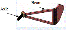 |
| The figure 4.1 shows Landing gear three dimensional modelling using Catia software. Both the components are represented separately. |
| Material Specifications: |
| Material : T7075-T6 (Aluminum Alloy) |
| - Density=2850kg/m3 |
| - Yield Strength=490N/mm2 |
| - Allowable Stress=392N/mm2 |
| Landing Gear Loads( Design Loads) |
| - Lift Load - 1000N |
| - Drag load – 450N |
| - Side load - 260N |
| - Torsion Load -20000N-mm |
| Meshed Plots |
| The structure is meshed using Hypermesh for good quality mesh. An RBE element is defined for load transfer. Coupling constraints and Beam elements are used for connecting the members. |
 |
| For modelling the Aluminium Rib, mid surface is extracted for main plate and the shell is meshed. Beam elements are used to connect the main shaft with the main plate through RBE3 elements. An RBE3 element with mass connection is done at the end of the wheel to simulation loads acting on the landing gear. Mid surface gives better results compared to three dimensional mesh due to lesser thickness compared to other dimensions. Generally for thin structures, rotational deformations also play important role in increasing the stress in the members which is neglected in the case of three dimensional meshing. Three dimensional elements are constrained by rotational degree of freedom or no representation for rotational displacements in its displacement function. |
| Assumptions: |
| 1. The material is assumed to elastic and homogenous |
| 2. The analysis has been carried out with in elastic limits |
| 3. Both Solid and shell concepts are applied for analysis |
| 4. All approximations applied to FEM are applicable for the analysis |
| 5. RBE3 element is used for load transfer. |
RESULTS AND DISCUSSIONS |
| Static Analysis Results |
| Analysis has been carried out with static loads and results are presented for displacements and vonmises stresses. Vonmises stress theory is the main failure theory to find the failure of the components or factor of safety in the problem. |
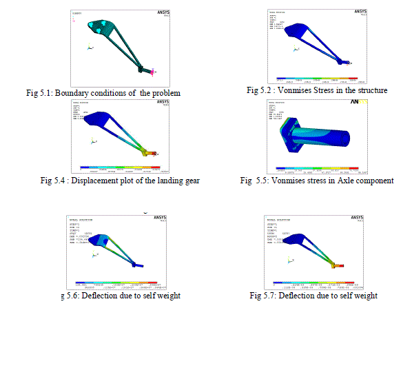 |
| The figure 5.1: shows applied boundary conditions on the problem. The load values are also shown. Translational forces in Newtons and torsional moment is represented in N-mm. The colour code is used to represent the problem boundary conditions. The top holes of landing gear are constrained in all the directions. Wheel end is applied with the loads through RBE3 elements. |
| The figure 5.3: shows developed vonmises stress in the structure. Maximum vonmises stress is around 353N/mm2. The stress is less than the yield stress of the material. So structure is safe for the given loads. But less factor of safety can be observed from the yield point of the material 440Mpa.Vonmises is the best theory of failure applied to the ductile materials. |
| The figure 5.4: shows displacement in the structure. Maximum displacement is around 22mm(0.022m). Maximum displacement is taking place at the loading region. The loads are applied at the wheel region of the axle component. The status bar shows variation of displacement in the problem through colour code. |
| The figure 5.5: shows maximum vonmises stress of 83.1457 N/mm2 on the axle component due to loading. The results shows safety of the problem. The maximum stresses are taking place at the connection region between the members. |
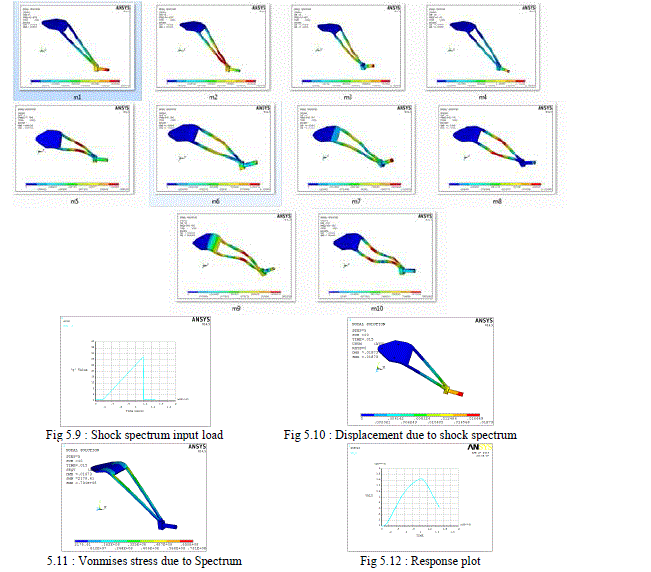 |
| The figure 5.6: shows maximum vonmises stress of around 3.44Mpa. This stress is much less the yield stress of the structure. The maximum stress is taking place near the curvature connecting to the wheel axle. |
| The figure 5.7: shows a maximum deflection of 1mm(0.001m) due to self weight of the landing gear. Maximum deflection is observed at the wheel end. |
 |
| The modal frequencies are extracted for 10 frequencies. The modal frequencies are required to calculate the resultant effect of modal spectrum vibration. The initial frequency of 15.6 Hz is corresponding to a speed of 936 rpm. This speed indicates resonance condition if the structure is excited with 936 rpm of the air craft. |
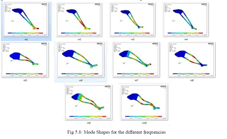 |
| The above mode shapes are corresponding to different modal frequencies of the system. Generally mode shapes are unpredictable and are not unique. But it shows the weaker directions of the problems when excited at resonant frequencies and helps in design of supports. Generally mode shapes are longitudinal, lateral, torsional and mixed mode. |
| Shock Spectrum Results: |
| The analysis has been carried out to find the effect of shock spectrum as specified by mil standards for air craft structures. The shock load is given as a saw tooth load for a time gap of 0.015seconds. |
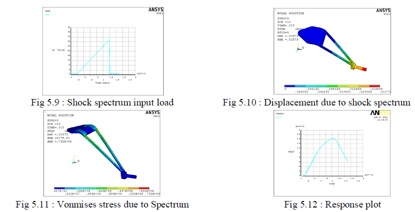 |
| The figure 5.9 : shows input load for the shock loading of the landing gear. A load 0f 30’g’ peak load is specified for the analysis without damping. The structure should with stand this load without failure for proper working of the landing gear. |
| The figure 5.10 : shows results maximum displacement of 18.73mm(0.01873m) taking place due to shock spectrum loads. Maximum displacement is taking place at the axle end. This is due to cantilever nature of the support. The status bar indicates the varying displacements in the structure. |
| The figure 5.11: shows spectrum response of the landing gear due to the given spectrum loads. Maximum stress of 73.1Mpa can be observed in the problem. |
| The figure 5.12 : shows response of the landing gear due to shock loads. The graph shows maximum response is taking place at 0.015seconds. |
 |
DISCUSSION |
| The landing gear is an essential component in the air craft operation. Almost 60% aircraft problems are linked to landing gear failures. In the present work, a landing gear is analysed for structural safety for the given design loads and compared to different materials. Initially the landing gear is modelled using Catia software for the given dimensions and later meshed using Hypermesh for good quality elements which will give better results. Later the meshed model is imported to Ansys for analysis. Initial structural analysis shows safety of the structure for given loads. Almost a stress of 357 Mpa is developing in the structure. But this stress smaller than yield stress of 440Mpa. Also self weight analysis analysis results shows very less (3.4Mpa) stress and a deflection of 1mm. A shock load is analysed as per mil standards to check the structural safety. The results shows 73.1Mpa stress in the structure along with a high deflection. Further composite replacement is done to check the strucrturla safety. |
CONCLUSION AND FEATURE SCOPE |
| The landing gear is analysed for structural integrity and for shock spectrum loads. The overall summary of the project is as follows. |
| Initially the geometry is built using Catia software for the required dimensions. The geometry is imported to hypermesh for good quality meshing(Hypermesh is having better options to maintain aspect ratio, skew angle, warpage and Jacobian). Generally accuracy of the solution depends on the mesh quality. Also tetrahedral elements can be avoided in Hypermesh. Initially the static structural analysis has been carried for extreme loads for deflection and vomises development. The results shows maximum stress development of 359Mpa which is less than the allowable stress of 440 Mpa. Further shock Spectrum analysis is carried out with modal analysis as the first step. A total of 10 modal frequencies are obtained which are required for finding the resonant condition. The analysis results for spectrum shows, a stress development of 89Mpa corresponding to time of maximum response. Further analysis is carried out with composite material for the same static, modal and shock spectrum analysis. The results shows higher strength of composite material compared to conventional aluminium material. All the results are presented with necessary graphs and pictures. |
FUTHER SCOPE |
| • The landing gear can be analysed for nonlinear loads |
| • Possible effect of thermal loads can be considered due to different materials expansion coefficients. |
| • Damper effects can be considered for further optimisation |
| • Possible interference effect can be considered for fatigue life of the landing gear. |
| • Other load cases specified in FAR23 and Mil standards also can be studied for structural safety. |
ACKNOWLEDGMENT |
| I would like to express my sincere gratitude to my Parents, beloved Principal, Head of the Department and my dynamic guide, without their support and prayers it would not have been possible to complete this project. Last but not least, I would like to thank my peers and friends who provided me with valuable suggestion to improve my project. |
References |
|