ISSN ONLINE(2319-8753)PRINT(2347-6710)
ISSN ONLINE(2319-8753)PRINT(2347-6710)
Amith Kalekar 1, S. B. Tuljapure 2
|
| Related article at Pubmed, Scholar Google |
Visit for more related articles at International Journal of Innovative Research in Science, Engineering and Technology
A bush pressing machine is designed for pressing bronze bushes into a pump frame or casing. Finite element method (FEM) based software ANSYS is used for modeling & analysis work. As the machine is symmetrical about a vertical plane, only half model is prepared using the modeling facilities available in ANSYS. Meshing is done using tetrahedral (Solid-45) elements. A force of 17.78 KN is applied on the job mounting plate & cylinder mounting plate in the form of pressure. Deflections and stresses are observed after the analysis. Both deflection & stresses are the allowable within limit. The stress values obtained by FEM are in well agreement with the analytical values.
Keywords |
| Finite Element Analysis, Press, Bush, Von Mises stress. |
INTRODUCTION |
| Due to the uneven cooling of the bronze bushes or due to stringent tolerances and some other reasons, the bush is not getting fitted easily in the pump frame in few cases. Manual insertion is leading to inclined entry of bushes. Thus due to these problems, a bush pressing machine is designed to assemble the bush & frame of the pump. The machine consists of two ‘C’ plates at sides. These plates are held together by frame strengthening plates. One hydraulic cylinder is mounted on the upper side. One job mounting plate is provided on the lower side to keep the jobs. Analysis of the machine is done to observe the stresses & deformation. |
II. LITERATURE REVIEW |
| A. G. Naik, N. K. Mandavgade (2012) incorporated design process successfully into a structural shape optimization problem. The aim of their work was reduction of bending stresses causing bending of frame of a hydraulic cotton lint bailing press by optimizing the Top & Bottom frame. Reduction of cost and Improvement in safety was another aim of their work. Software ANSYS was used for this work. Due to new design a reduction in weight of frame was 13%. |
| H.N.Chauhan & M.P.Bambhania (2013) designed & analyzed frame of a 63 tonne power press machine using Finite Element method. Due to the impact loading at the end of the bolster plate there was development of a crack at the corner and stress generated was more due to continuous loading and stress concentration. Modifications were done by introducing the fillets of proper size. Also plate thickness was reduced which saved material. |
| Ankit H Parmar and et al (2014) performed optimization of a hydraulic press structure to decrease total mass of structure while assuring adequate stiffness. A method of structure optimization for hydraulic press was proposed in order to reduce mass while assuring adequate stiffness. Key geometric parameters of plates which have relatively larger impacts on mass and stiffness were extracted as design variables. In order to research relationship between stiffness, mass and design variables, common batch file was built by CREO and analysis was done in ANSYS. Top plate, movable plate and column design and analysis were done. A reduction of weight was 42 % keeping the stresses & deflection within limit. |
| Bhavesh Khichadia, Dipeshkumar Chauhan (2014) took review on design and analysis of mechanical press frame. They dealt with the analytical method and corresponding design and analysis of mechanical press frame. Modeling of press frame has created by the CAD software and according to the modeling structure failure analysis done by FEA tool. Stress distributions in press frame have been found out by the analytical and simulation methods |
| Reference data were used for the new design for modification of a new press structure. With regard to design specification, stress distribution, deflection, optimization, ergonomics, stiffness and rigidity was focused on recent design and development in press frame obtained from structural components of press machine frame. |
| B. Parthiban and et al (2014) designed a ‘C’ type hydraulic press structure and cylinder. They analyzed press frame and cylinder to improve its performance and quality of press working operation. The frame and cylinder were modeled by using software CATIA. Structural analysis was done using analysis software ANSYS. An integrated approach was developed to verify the structural performance and stress strain distributions were plotted by using ANSYS software. According to the structural values the dimensions of the frame and cylinder were modified to perform the functions satisfactory. |
| D. Ravi (2014) analyzed a power press of 10 tonne capacity under static condition. The modeling of the C- frame power press was done using Pro/E software. The 3D model of the power press was analyzed in static condition to find the stresses and deflections in the structure. Later part involved the reduction in weight of the power press by varying or reducing the thickness of frame and bed and the press was analyzed in static condition to find the results. The result obtained from analysis package is within the limit. |
| Santoshkumar S. Malipatil and et al (2014) made an attempt with the objective to reduce the volume of material of a press. They considered an industrial application project consisting of mass minimization of H-frame type hydraulic press. ANSYS software was used for this analysis the main aim was to reduce the cost of the Hydraulic presses without compromising on the quality of the output. With regarding to design specification, stress distribution, deflection, and cost, were focused on optimized design. The methodology followed in this work was comparison of stresses induced in machine for different thickness used for construction of frame and column of the H-frame type hydraulic press. |
III. DESIGN OF BUSH PRESSING MACHINE |
| Following are the figures of frame & bush. The tolerances provided for hole in the frame & bush outer diameter are studied in detail. |
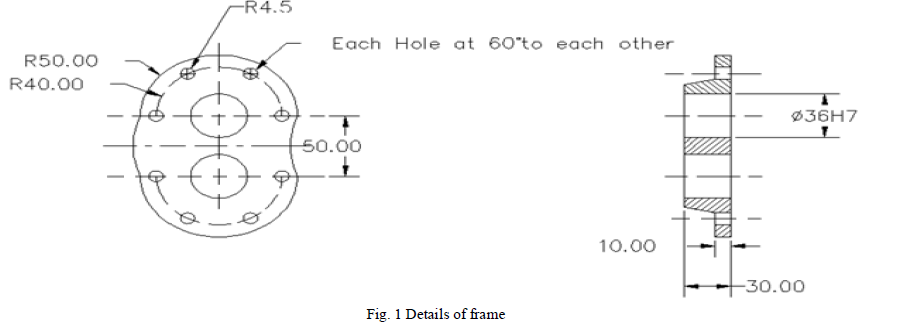 |
| The material of the frame shown in the above figure is Cast iron. Bush is to be fitted in the hole of diameter 36 mm. Only important dimensions & tolerances are shown in the figure to reduce the complications. |
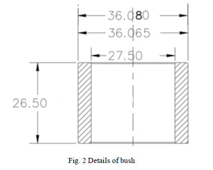 |
| The material of the bush used is Phospher Bronze. Here also only important dimensions with tolerances are shown. The diameter of the bush is larger than 36 mm to get the require fit. |
Design of Press Body/Frame |
| The permissible tensile stress for the selected ‘C’ plates is given by |
| For design of the bush pressing machine, the maximum interference between bush & hole in pump frame after nitrogen cooling of bushes is determined. But the machine is designed for maximum interference which can be obtained by normal press fitting operation for the present diameter of bush. This interference is slightly higher than the one which is obtained due to nitrogen cooling of bushes. The force required for this operation is 17.78 KN. Since two identical plates (C shaped) are taken, the force on each plate is (17.78/2) = 8.89 KN These ‘C’ plates are subjected to direct tensile stress & bending stresses. The stresses are maximum at the inner fiber. At the inner fibre, |
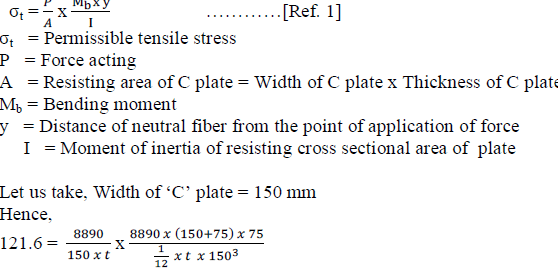 |
| t = 4.87 mm Let us take a standard 6 mm thick plate for C plates of the body. Considering the height of the normal person, the space required for mounting the casting frame & bushes, & the free space for the hand movements, mounting of hydraulic cylinder etc. other dimensions of the C plate are finalized and are as shown below in the figure. |
Design of job mounting plate |
| The maximum force acting on the plate is 17.78 KN. Let us take 250 mm x 300 mm (width) as area of mounting plates of job. Now, load acts at the centre of the plate. So, this is a case of a simply supported beam of length 300 mm with a central load of 17.78 KN. Thus, the plate will be only under bending load. |
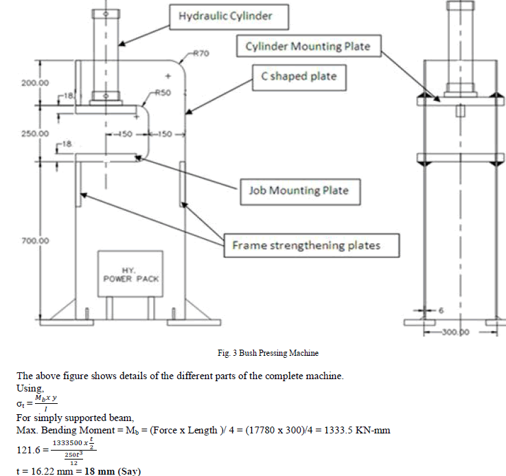 |
| Now the dimensions of the job mounting plate are 250 mm x 300 mm x 18 mm The calculations done for job mounting plate are also applicable to hydraulic cylinder mounting plate. This plate will have same dimensions as job mounting plate. |
| Frame strengthening plates: Four plates are used for keeping two ‘C’ plates together & strengthening the body of the machine. The dimensions of these plates are 300 mm (width) x 200 mm (height) x 10 mm (thickness). Two plates are mounted in the front side, one at the top side & one at the bottom side. One plate is mounted at the back side of the machine. Leveling and installation plates are provided at the four corners of the base. |
IV. FINITE ELEMENT ANALYSIS |
| Finite element analysis is a powerful tool in the field of engineering. Initially, finite element analysis was used in aerospace structural engineering. The technique has since been applied to nearly every engineering discipline from fluid dynamics to electro-magnetics. While finite element analysis offers another way to analyze structures, it requires an understanding of the program and subject being modeled. If the operator does not use the correct model, time is wasted and more importantly the data is useless. Finite element analysis is one solution to the problem. In finite element analysis the structure is broken up into small pieces that are easier to analyze. In the case of the cylinder it might be broken up into small cubes or plates called elements. All of the elements make up the mesh. Each of these elements can be easily solved for by using simple equations for stress and strain. As the number of elements increases (increasing mesh size), their size decreases and the solution will grow more accurate. |
Analysis of C plate: |
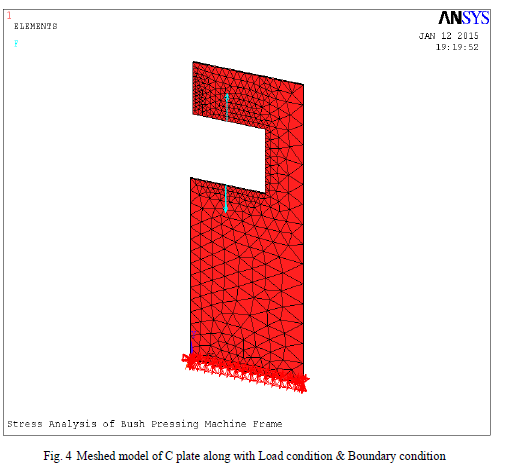
| Initially ‘C’ plate of the machine is modeled & analyzed to check the suitability of element type & mesh density. The meshed model along with the load condition & boundary condition is shown in the following figure. |
 |
| Meshing: Model is meshed using 8 Node Brick 45 (SOLID45) elements. The geometry of this element is as shown in the figure 5. The tetrahedral option is used for the present problem. Solid 45 is used for the 3-D modeling of solid structures. The element is defined by eight nodes having three degrees of freedom at each node: translations in the nodal x, y, and z directions. The element has plasticity, creep, swelling, stress stiffening, large deflection, and large strain capabilities. At the inner fibre, |
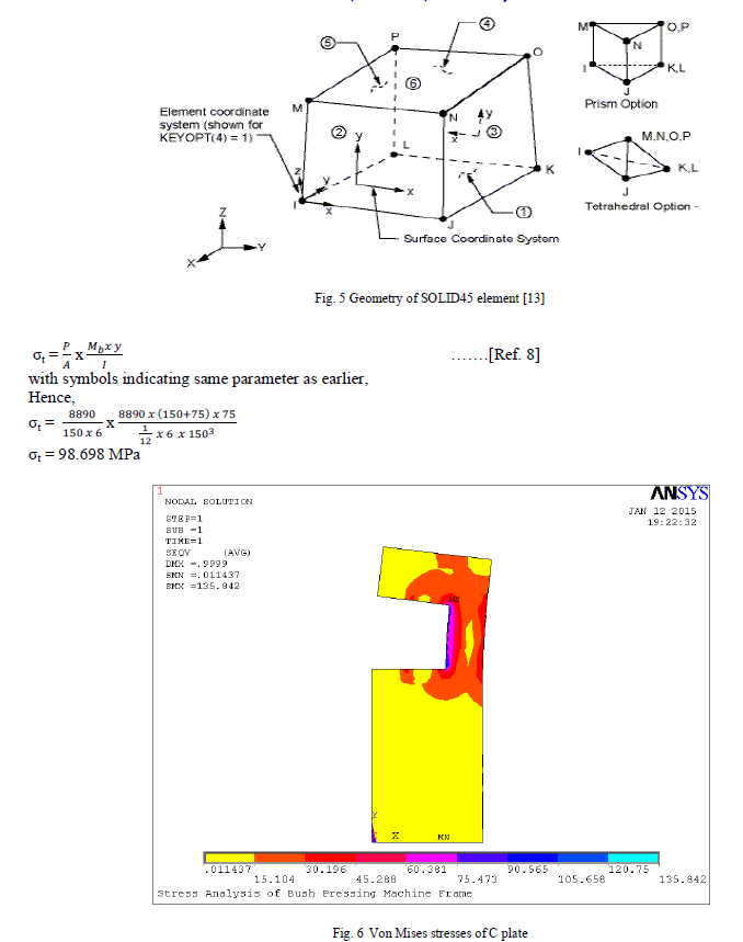 |
| At the inner fiber, the stress values should be near to 98.698 MPa on the inner side of the C plates. Figure 6 shows the stresses in the C plate. The stresses at the inner fiber are as per the calculations. |
| As the stress values obtained on the ‘C’ plate are as per the analytical values, it can be said that the type of element chosen & mesh density for the present structure are correct. Hence the analysis of complete frame is can be done taking same element & mesh density. |
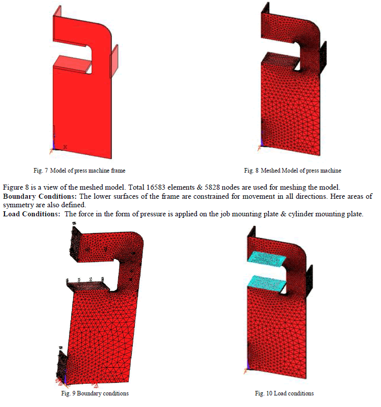
| Modeling of the bush pressing machine: The modeling facilities available in ANSYS were used for the present work & found to be sufficient. As the frame or body of the machine is symmetrical along a vertical plane, only half model is prepared & symmetry plane is defined. This will reduce the computational time. Figure 7 shows the model prepared for finite element analysis. |
 |
V. RESULTS & DISCUSSIONS |
| During post-processing, deformation, stresses etc are observed. Deformed shape: Figure 11 shows the deformed shape of the machine frame along with the un-deformed shape. The maximum deformation is 1.053 mm. This maximum deformation will occur at the highest interference fit in press fit category. This situation will not come as due to nitrogen cooling of the bushes interference is going to reduce much. In those cases, actual deformation will be far less than the above value. This deformation is due to the unsupported upper part. In case of lower region, it is resting on ground. So deformation will be lesser in lower region. Thus the present dimensions of different parts of press machine are found to be satisfactory. |
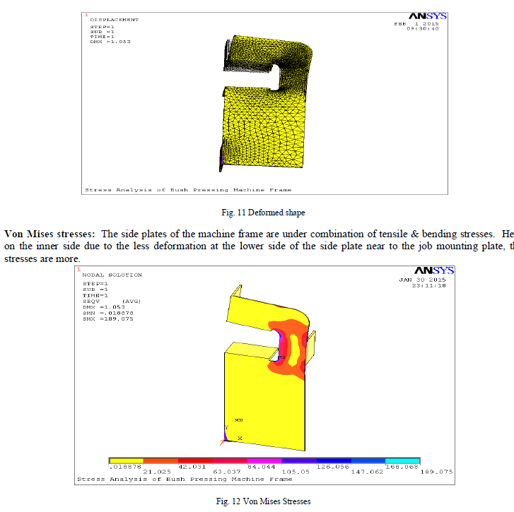 |
| Figure 12 shows Von Mises stresses for machine frame. The maximum stress is 189.075 MPa. This is occurring at the lower fillet region. |
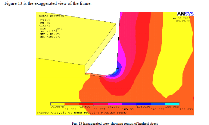 |
| It is clearly showing maximum stresses at the lower fillet. Still the stresses are within limit. So the tructure is safe. |
VI. CONCLUSION |
| Following are the conclusions. The deformation & stresses for the designed bush pressing machine are within limit. The deflection in the upper region is more due to unsupported part. The stress is more in the lower region as there is less deformation. Maximum stress occurs at the fillet in the lower region |
References |
|