International Journal of Innovative Research in Science, Engineering and Technology
ISSN ONLINE(2319-8753)PRINT(2347-6710)
ISSN ONLINE(2319-8753)PRINT(2347-6710)
Manjunath T V1, Dr Suresh P M1
|
| Related article at Pubmed, Scholar Google |
Visit for more related articles at International Journal of Innovative Research in Science, Engineering and Technology
The disc brake is a device for slowing or stopping the rotation of a wheel. Repetitive braking of the vehicle leads to heat generation during each braking event. Transient Thermal and Structural Analysis of the Rotor Disc of Disk Brake is aimed at evaluating the performance of disc brake rotor of a car under severe braking conditions and there by assist in disc rotor design and analysis. Disc brake model and analysis is done using ANSYS workbench 14.5. The main purpose of this study is to analysis the thermomechanical behavior of the dry contact of the brake disc during the braking phase. The coupled thermal-structural analysis is used to determine the deformation and the Von Mises stress established in the disc for the both solid and ventilated disc with two different materials to enhance performance of the rotor disc. A comparison between analytical and results obtained from FEM is done and all the values obtained from the analysis are less than their allowable values. Hence best suitable design, material and rotor disc is suggested based on the performance, strength and rigidity criteria.
Keywords |
| Disc Flange, ANSYS Workbench, Structural, Thermal Analysis, Disc Brake |
INTRODUCTION |
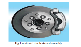
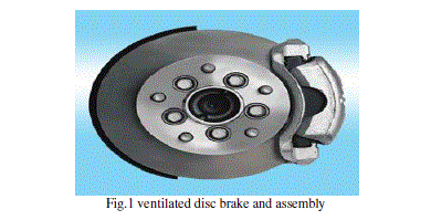
| In today’s growing automotive market the competition for better performance vehicle is growing enormously. The racing fans involved will surely know the importance of a good brake system not only for safety but also for staying competitive. The disc brake is a device for slowing or stopping the rotation of a wheel. A brake disc usually made of cast iron or ceramic composites includes carbon, Kevlar and silica, is connected to the wheel and the axle, to stop the wheel [1- 3]. A friction material in the form of brake pads is forced mechanically, hydraulically, pneumatically or electromagnetically against both sides of the disc. This friction causes the disc and attached wheel to slow or stop. Generally, the methodologies like regenerative braking and friction braking system are used in a vehicle . A friction brake generates frictional forces as two or more surfaces rub against each other, to reduce movement. Based on the design configurations, vehicle friction brakes can be grouped into drum and disc brakes. If brake disc are in solid body the heat transfer rate is low [4-6]. Time taken for cooling the disc is low. If brake disc are in solid body, the area of contact between disc and pads are more. In disc brake system a ventilated disc is widely used in automobile braking system for improved cooling during braking in which the area of contact between disc and pads remains same [7,8]. Brake assembly which is commonly used in a car as shown in fig1. |
 |
II. CALCULATION FOR INPUT PARAMETERS |
| In the aspect of the car accident prevention, the braking performance of vehicles has been a critical issue. The rotor model heat flux is calculated for the car moving with a velocity 27.77 m/s (100kmph) and the following is the calculation procedure. Data: |
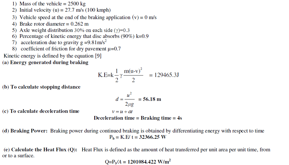 |
II. ANALYTICAL TEMPERATURE RISE CALCULATIONS |
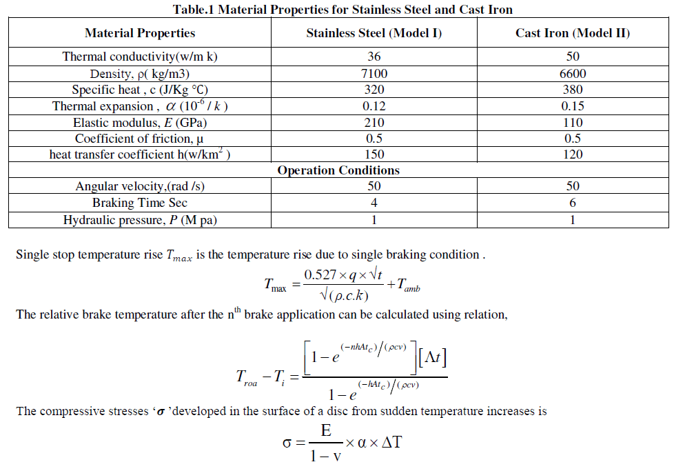
| The contact area between the pads and disc of brake components, heat is generated due to friction. For calculation of heat generation at the interface of these two sliding bodies, two methods are suggested on the basis of “law of conservation of energy which states that the kinetic energy of the vehicle during motion is equal to the dissipated heat after vehicle stop” [7]. The material properties and parameters adopted in the calculations are as shown in table1 [9]. |
 |
III. FINITE ELEMENT ANALYSIS |
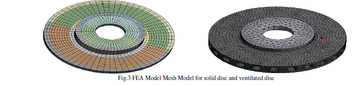
| The finite element method has become a powerful tool for the numerical solutions of a wide range of engineering problems. It has been developed simultaneously with the increasing use of the high- speed electronic digital computers and with the growing emphasis on numerical methods for engineering analysis. In this step it defines the analysis type and options, apply loads and initiate the finite element solution. This involves three phases: ïÃÆÃË Pre-processor phase ïÃÆÃË Solution phase ïÃÆÃË Post-processor phase The ANSYS Workbench, together with the Workbench projects and tabs, provides a unified working environment for developing and managing a variety of CAE information and makes it easier for set up and work with data at a high level. Workbench includes the following modules “ANSYS Design Space” is referred to as Simulation “ANSYS AGP” is referred to as Design Modeler and ”ANSYS Design explorer” referred to as Design explorer. Workbench provides enhanced interoperability and control over the flow of information between these task modules. Various tools and techniques are incorporated for efficiently manage to large models. Like tree filtering tagging tree Objects, connections worksheet, object generator, submodeling. Data can be transferred from a 2D coarse model [Full Model] to a 3D submodel. Submodeling is available for structural and thermal analysis types with solid geometry. |
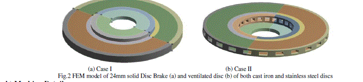
| a) FEM Model of Solid Disc and Ventilated Disc Brake The finite element model of disc brake constructed for the dimensions as shown in fig.2 the inner radius, outer radius and flange thicknesses of discs are as 0.08, 0.0131 and 0.024m for cast iron and stainless steel respectively to both cases solid and ventilated disc. |
 |
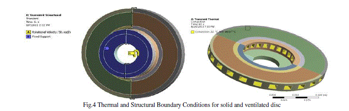
| c) Thermal and Structural Boundary Conditions The boundary conditions are introduced into module ANSYS Workbench, by choosing the mode of simulation and by defining the physical properties of materials and the initial conditions of simulation. In this work, a transient thermal analysis will be carried out to investigate the temperature variation across the both disc by applying heat flux value for repeated braking applications using ANSYS. Further structural analysis is carried out by coupling thermal analysis. In addition convection heat transfer coefficient is applied at the surface of the ventilated disc for the analysis as shown in fig 4. |
 |
IV. RESULTS AND DISCUSSIONS |
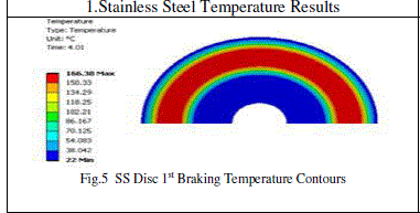
| To validate the present models, a transient thermal analysis behavior of disc brake was performed for the operating condition of the constant hydraulic pressure P =1Mpa and angular velocity ïÃÂ÷ = 50 rad/s (drag brake application) during 10 seconds. The ANSYS simulation is obtained in 6 repeated brake applications. One cycle is composed of braking time of 4sec and constant speed driving. The time step Δt =0.001 sec was used in the computations. In each process, the heat flux distribution on the friction surfaces after time t=4 sec does scarcely occur and then the steady state is reached. The hydraulic pressure was assumed to linearly increase to 1MPa by 1.5 sec and then kept constant until 4sec. Also, the angular velocity was assumed to decay linearly and finally become zero at 4sec. The results obtained from analytical and FEM solutions are compared for both transient thermal and structural behavior of the model. Finally the best model is suggested. In addition, based on disc brake performance a ventilated radial vanes disc brake analysis of two different materials is carried out for 6 braking conditions. Comparisons of solid discs case I and ventilated discs case II are performed to validate the results. |
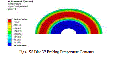
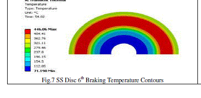
CASE I: Solid Disc |
 |
 |
| The distribution of the total distortion in solid stainless steel cast iron disc brake is shown in fig11. The scale of values of the deformation varies from 0 μm with 0.06mm which corresponds to the time of braking. After the 6th braking, the maximum deflection induced is 0.0608mm in SS disc and 0.059 in C I disc, which is less than the allowable deflection 0.5mm. During the total time simulation of braking for a full disc presents the distribution of the constraint equivalent of Von Mises Stresses to various moments of simulation as shown in fig12. The scale of values varies from 0 MPa to 255MPa in stainless steel disc and 142 MPa in cast iron disc, which is the maximum thermal stress induced at maximum temperature rise after 6th braking application. |
 |
 |
| The distribution of the total distortion in stainless steel and cast iron ventilated disc brake is shown in fig21. The scale of values of the deformation varies from 0 μm to 0.0128mm and which corresponds to the time of braking. After the 6th braking, the maximum deflection induced is 0.0128mm in SS ventilated disc and 0.098mm in C I ventilated disc, which is less than the allowable deflection 0.5mm. The distribution of the constraint equivalent of Von Mises Stresses The scale of values varies from 0 MPa to 288MPa for in stainless steel disc and 110 MPa in cast iron disc. Which is the maximum thermal stress induced at maximum temperature rise 320 and 283 after 6th braking application respectively. |
V. COMPARISON THE RESULTS OF SOLID AND VENTILATED DISC |
 |
| Comparing the different results of temperature rise, deflection, and stress field obtained from analysis it shows that the ventilated cast iron disc has reduction in temperature, deflection and stresses. It is concluded that ventilated type cast iron disk brake is the best for the present application. |
VI. CONCLUSIONS |
| Comparing the different results of temperature rise, deflection, and stress field obtained from analysis it shows that in the ventilated cast iron disc reduction in temperature, stresses and deformation by 31.47% and 22.5% 8% respectively than the solid disc. It is concluded that ventilated type disk brake is the best for the present application. All the values obtained from the analysis are less than their allowable values. Hence the brake disk design is safe based on the strength and rigidity criteria. |
References |
|