International Journal of Innovative Research in Science, Engineering and Technology
ISSN ONLINE(2319-8753)PRINT(2347-6710)
ISSN ONLINE(2319-8753)PRINT(2347-6710)
| Prof.D.R.Patil1, Sourabh Jogalekar2, Rohit Jagtap3, Sagar Jadhav4 Assistant Professor, Dept. of Electrical Engineering, Walchand College of Engineering, Sangli,Maharashtra, India1 Final year B.Tech Student, Dept. of Electrical Engineering, Walchand College of Engineering, Sangli,Maharashtra, India2, Final year B.Tech Student, Dept. of Electrical Engineering, Walchand College of Engineering, Sangli,Maharashtra, India 3 Final year B.Tech Student, Dept. of Electrical Engineering, Walchand College of Engineering, Sangli,Maharashtra, India4 |
| Related article at Pubmed, Scholar Google |
Visit for more related articles at International Journal of Innovative Research in Science, Engineering and Technology
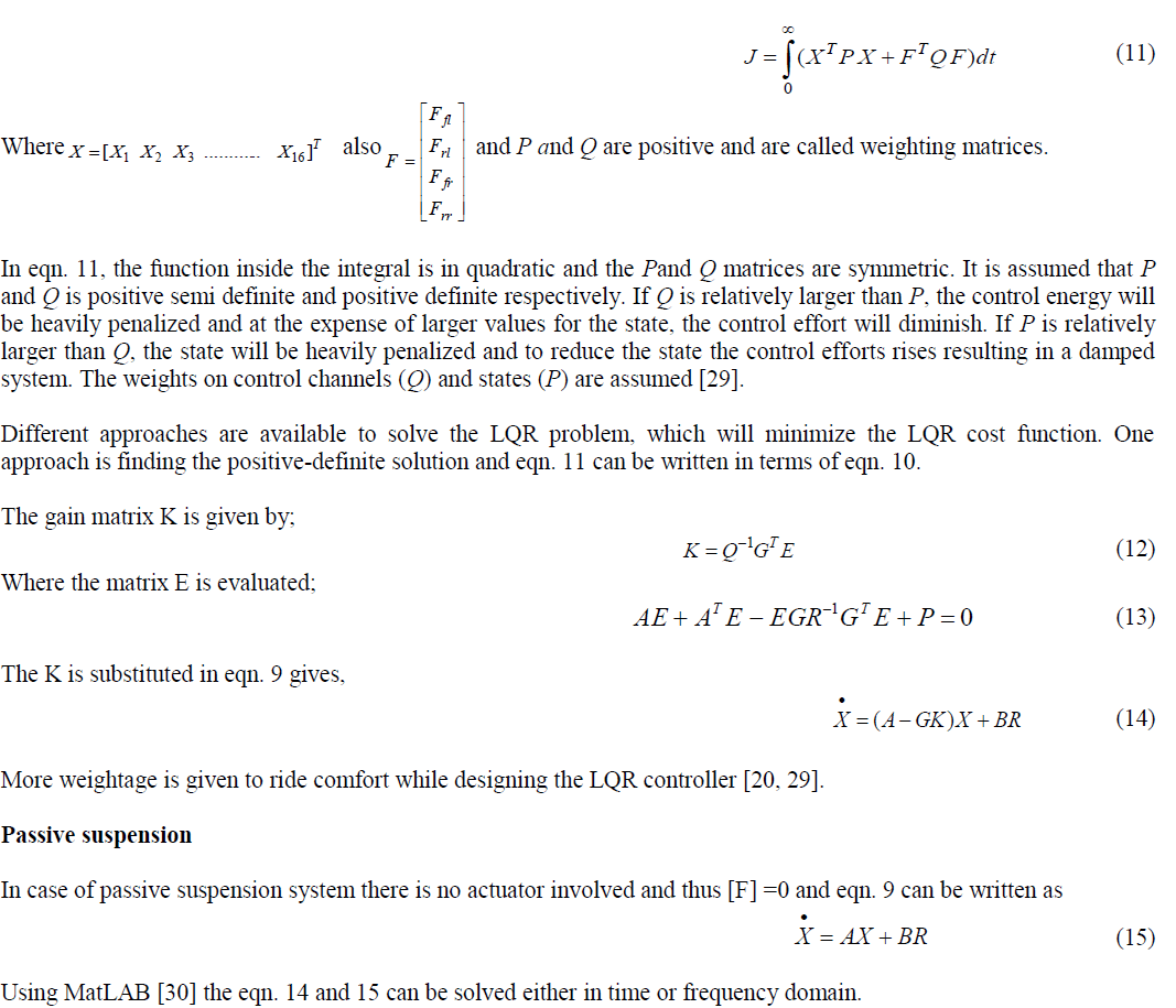
This paper presents a speed-sensorless separately excited dc motor drive which uses the simple observer [6] to estimate the rotor speed & also involves the design and simulation of a microcontroller-based sensorless speed control of permanent magnet DC motor. The basic feedback circuit in closed loop speed control of motor is replaced by an observer which estimates the speed(ω) by using motor parameters(R, J, k,L) & line variables(V,I, dIa /dt). The speed control is achieved by using armature voltage control, which is controlled by changing duty ratio of chopper.
Keywords |
||||||||||||
| Sensorless, Observer, Estimation, Current controller | ||||||||||||
I.NOMENCLATURE |
||||||||||||
 |
||||||||||||
INTRODUCTION |
||||||||||||
| DC drives are widely used in applications requiring adjustable speed, good speed regulation and control. Energy savings and process control are the two primary reasons for using adjustable speed drives. Most concepts in control theory are based on having sensors to measure the quantity under control. In fact, control theory is often taught assuming the availability of near-perfect feedback signals. Unfortunately, such an assumption is often invalid. Physical sensors have shortcomings that can degrade a control system [2]. | ||||||||||||
| There are at least four common problems caused by sensors [5]. | ||||||||||||
| I. Sensors are expensive. Sensor cost can substantially raise the total cost of a control system. In many cases, the sensors and their associated cabling are among the most expensive components in the system. | ||||||||||||
| II. Sensors and their associated wiring reduce the reliability of control systems. | ||||||||||||
| III. Some signals are impractical to measure for example, when trying to measure the temperature of a motor rotor. | ||||||||||||
| IV. Sensors usually induce significant errors such as stochastic noise, cyclical errors, and limited responsiveness. | ||||||||||||
| Thus tachogeneratorless speed control may overcome some of the above drawbacks that may be induced due to introduction of tacho generator. So, this paper proposes applications for systems where it is not feasible to introduce mechanical transducers (e.g. system is already set up & there is no space for transducers - space saving), moreover in systems where the drawbacks of tacho generators (cabling, noise, error, cost, maintenance, vibrations) cannot be tolerated, this system can be implemented. | ||||||||||||
III.PROPOSED SYSTEM |
||||||||||||
| I. ESTIMATION OF ARMATURE SPEED | ||||||||||||
| Applying Kirchhoff’s voltage law to motor circuit [3] | ||||||||||||
 (1) (1) |
||||||||||||
| And we know for a DC machine having constant flux [3] | ||||||||||||
 (2) (2) |
||||||||||||
| Substitute eqn. (2) in eqn. (1) and solving for ,we get estimated speed as, | ||||||||||||
 (3) (3) |
||||||||||||
| Here cascade current controller is used for better dynamic response. The current controller used is Hysteresis current controller [1]. | ||||||||||||
| Now current reference is generated using motor parameters as k, J | ||||||||||||
 (4) (4) |
||||||||||||
| Being PMDC motor | ||||||||||||
 |
||||||||||||
| So equation (4) can be written as, | ||||||||||||
 (5) (5) |
||||||||||||
| Where Tm is the motor required to attain the reference speed for given acceleration Motor parameters can be obtained from datasheet of motor, they are also calculated using some typical tests given in TABLE I [3]. | ||||||||||||
IV.WORKING OF CLOSE LOOP SYSTEM |
||||||||||||
| Voltage Va and current Ia are sensed via voltage & current sensors. The ADCs convert these V & I values to digital signals recognizable by microcontroller. It monitors the values of V, I and calculates |
||||||||||||
| Then we may use PI algorithm to find the current reference I* or as explained in equation (5).The actual line current I is already read & the error=I-I*is found. According to sign of error (either positive or negative) the IGBTs to be switched are determined and accordingly the PWM pulses are generated. These pulses are conditioned through IGBT driver circuit & given to the base of respective IGBTs of the Chopper (2 Quadrant). | ||||||||||||
V.Hysteresis current controller |
||||||||||||
| The current limits are set earlier (Hysteresis band) and the IGBTs are switched so that line current neither exceeds the upper limit of band nor goes below the limit. This current controller is in cascade with speed controller which provides good dynamic response such as less settling time, overshoot, oscillations etc, for different loading conditions | ||||||||||||
VI.SIMULATION RESULTS AND DISCUSSION |
||||||||||||
| The speed of armature is estimated without using any actual speed sensor/tacho generator, solely with the help of electrical signals such as Va, Ia, and parameter constants such as Ra,k,La. | ||||||||||||
| Fig.5 shows that actual and estimated speed characteristics are matching. So this estimation technique can be a good substitute for tacho generator based closed loop systems. | ||||||||||||
VII. CONCLUSION |
||||||||||||
| In this paper, we proposed a speed-sensorless separately excited dc/PMDC motor drive which uses the simple observer to estimate the rotor speed .Simulation results shows that the aspects of control variable such as steady state error, overshoot, settling time, oscillations are within accepted limits. Elimination of the sensor (tachogenerator) further reduces cost and increases reliability. Furthermore, sensorless control is the only choice for some applications where those sensors cannot function reliably due to harsh environmental conditions and a higher performance is required such as power optimized aircraft [7], adding important benefits in energy consumption, weight savings, easy assembly procedures and maintenance. | ||||||||||||
Tables at a glance |
||||||||||||
|
||||||||||||
Figures at a glance |
||||||||||||
|
||||||||||||
References |
||||||||||||
|


