International Journal of Innovative Research in Science, Engineering and Technology
ISSN ONLINE(2319-8753)PRINT(2347-6710)
ISSN ONLINE(2319-8753)PRINT(2347-6710)
Jyoti Lalotra1, Abhinav Sharma2, Saleem khan3, Parveen Lehana4
|
| Related article at Pubmed, Scholar Google |
Visit for more related articles at International Journal of Innovative Research in Science, Engineering and Technology
This paper describes the concept of harmonics in power systems. Investigations are carried out to analyse the effect of loads (combination of resistive, inductive and capacitive) on the IGBT based Voltage stabilization. Harmonic distortions in the input and output voltage of the system is calculated. Eight Different combinations of the load are taken inductance ranging from approximate value of 1.232H to 269.1mH keeping resistance 36 Ω and capacitance 2.5μF. Input and output voltages waveforms were recorded processed using Gold wave and digital signal processing software respectively. The sampling rate and duration of measurement are kept at value of 16000 and 1s respectively.
Keywords |
| Harmonic distortion, IGBT, load effect, power system, voltage stabilization. |
INTRODUCTION |
| Harmonics have existed in power systems for many years. In the past, most electrical equipment is using balance linear load. A linear load in a power system distribution is a component in which the current and voltage are perfect sinusoidal [1]. Examples of linear loads are induction motor, heaters and incandescent lamps [2]. But the rapid increase in the electronics device technology such as diode, thyristors, etc cause industrial loads to become non-linear. These components are called non-linear load [3]. The non-linear load connected to the power system distribution will generate harmonics current and voltage [4] [5]. Power system harmonic are not new fact. It is mainly caused by saturation of loads such as transformers, industrial arc furnaces, cables, Switching mode power supplies and other devices [6][7]. |
| A harmonic is a sinusoidal component of a complex wave or quantity having a frequency that is an integral multiple of the fundamental frequency [8]. |
| fh ïÃâ¬Ã½ (h)ïÃâô (Fundamental frequency) |
| where h is an integer |
| Harmonic distortions waveform extremely alters the shape of the sinusoid. However, no matter the level of complexity of the fundamental wave, itâÃâ¬ÃŸs just a combination of multiple waveforms called harmonics. |
| The research work is carried out to investigate the effect of impedance i.e. change in the inductance keeping capacitance and resistance constant on the designed IGBT based power system. Signal processing technique is used to evaluate the effect of the impedance and calculation of total harmonic distortion (THD). |
II. REDUCTION OF HARMONIC DISTORTION |
| There are many way to reduce the harmonics but the main aim to improve the power quality by the use of passive filter connected at the sensitive load terminals. If we use the active filter than we achieve good harmonic and improve the power quality and also reduced the harmonic by injected voltage by using series Compensation is more effective [9]. |
| Harmonic solution is divided into two ways drive and rectifier solutions and solutions for Commercial facilities for solution of harmonics. |
A. Drive and rectifier |
| ïÃâ÷ It has low cost current harmonics |
| ïÃâ÷ percent of impedance are available at different values |
| ïÃâ÷ Increased the protection for AFD and its semiconductors are provided |
| ïÃâ÷ Reduction in voltage and current harmonics by using source reactance. |
| ïÃâ÷ less voltage drop |
B. Solutions for commercial facilities |
| ïÃâ÷ Decrease phase current |
| ïÃâ÷ Reduce neutral current [10]. |
| There are some popular technologies that help to reduce the harmonics: |
A. Passive filter |
| Passive filter is made up of several different components like resistors, capacitors and inductors. It is simply apply for a given transfer function. Passive filter is best because they require less power supplies and little noise occurs as compared to active gain elements [11]. |
B. Active filter |
| Active filters use, specially op amps with resistors and capacitors Active filters can have high input impedance, low output impedance the design of active filter are simpler than passive filter. This is most important attribute is that they lack inductors, thereby help to reduce the harmonics [12]. |
C. The switched – capacitor filter |
| Another types of filter are used to reduce harmonics is switched and capacitor types filter .the switched filter are used for last decade. Switched capacitor filters need external capacitors or inductors and their cut off frequencies by an external clock frequency [13]. |
D. Steps for reducing the telephone interferences |
| The steps are as following: |
| ïÃâ÷ Increase spacing |
| ïÃâ÷ Improve balance of AC power lone by transmission |
| ïÃâ÷ Ground based telephone circuit should be replaced |
| ïÃâ÷ Use of underground telephone cables |
| ïÃâ÷ Reduction of electromagnetic coupling in between the electric power system and electronics circuit [14] [15]. The harmonic elimination technique is very suitable for inverters control. To apply this technique, the low harmonic distortion output waveform without any filter circuit is possible. Switching devices are help to, turn on and off only cycle in per unit time [16].ANN can help to eliminate the harmonic. One more method that help to improve power factor and eliminate the harmonics is Dynamic voltage restorer (DVR) this is very efficient and effective device are used in power system. A DVR is a solid state inverter based on injection of voltage in series with a power distribution system [17]. |
III. METHODOLOGY |
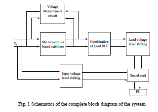 |
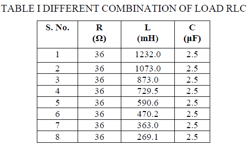
| IGBT and other peripheral and the output from microcontroller based stabilizer is applied to load block. In this block load consists of series combinations of resistor, capacitor and inductor. Different combinations of impedance are taken shown in Table 1. Eight different combinations of the load are taken inductance ranging from 1.232H to 269.1mH keeping resistance 36 Ω and capacitance 2.5μF. The input and output voltages are recorded in the PC using sound card and voltage level shifting block. This block is required to bring down the voltage level from hundreds of volts to millivolts, so that it can be applied to sound card. Signals are recorded and processed using Gold wave and digital signal processing software respectively. The sampling rate and duration of measurement are kept at value of 16000 and 1s respectively. |
 |
IV. RESULT AND DISCUSSION |
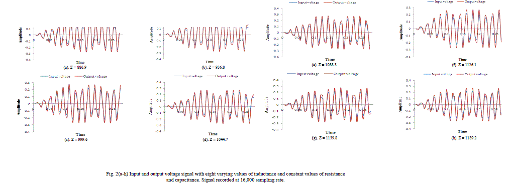
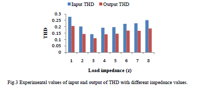
| The experiment is carried out to investigate the effect of RLC loads on IGBT based stabilization and analysis the harmonic distortion in the input and output caused by different combinations of inductive, capacitive and resistive load. Eight different Combinations of load are taken in the experiment are shown in Table 1. Input and output voltages for various combinations were recorded for limited time duration of 1 sec with sampling rate of 16,000. The signals were processed using signal processing technique to evaluate the harmonic distortion. Segment of the signals are taken and harmonic distortion in them are calculated. Fig. 2(a) to Fig. 2(h) represents the segmented input and output voltage waveforms for eight different combinations of the load with duration of 0.25s. The calculated value of impedance, input and output total harmonic distortion for eight different load values are given in Tables 2. The calculated experimentally values of input and output of THD are plotted in Fig. 3 with different impedance values. |
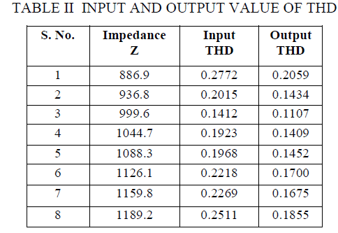 |
| As the values of the impedance is decreased i.e. variation in the value of inductance from Henry (H) to mH, the input and output value of total harmonic distortion (THD) rises giving maximum and minimum values of 0.2772 and 0.1412 and output value is 0.2059 and0.1107 respectively. There is also some difference in input and output value of THD is seen in the plot for certain combinations which may arise due to leakage of the inductive or capacitive components. Form the calculated values of THD in input and output it is observed that the harmonic distortion in the output is comparatively less than the input. |
 |
 |
V. CONCLUSION |
| In this research work carried out effect of loads (combination of resistive, capacitive, and inductive) on the IGBT based voltage stabilization causing harmonic distortion is investigated. Eight different combinations of the load are taken with varying the values of inductance keeping resistance and capacitor is constant. Input and output voltages were recorded for all combinations using Gold wave software with sampling rate of 16,000. The designed microcontroller and IGBT based power stabilization are reduced the harmonic distortion in the output. The maximum value of THD in the input is 0.2772 and corresponding output THD is 0.2059. |
References |
|