ISSN ONLINE(2319-8753)PRINT(2347-6710)
ISSN ONLINE(2319-8753)PRINT(2347-6710)
Nikhil R N 1, Sateesh Kumar H C2
|
| Related article at Pubmed, Scholar Google |
Visit for more related articles at International Journal of Innovative Research in Science, Engineering and Technology
LTE is a standard for wireless data communications technology and an evolution of the GSM/UMTS standards. Long Term Evolution (LTE), commonly referred to as 4G or next generation wireless communications is the new standard for nationwide public safety broadband. This standard will allow access to digital technologies and deliver expanded capabilities to public safety practitioners in the field. LTE (an initials of Long Term Evolution), is a standard for wireless communication of high-speed data for mobile phones and data terminals. It is enhancement on the GSM/EDGE and UMTS/HSPA network technologies, by increasing the capacity and speed using new modulation techniques. The standard is developed by the 3GPP (3rd Generation Partnership Project) and is specified in its Release 8 document series
Keywords |
| Long Term Evolution, Evolved Packet Service, eNB, Mobility Management Entity, User Equipment, EUTRAN |
INTRODUCTION |
| The LTE standard supports fast speeds. This describes the standard for the over-the-air component of mobile broadband. LTE was first used in the commercial broadband world, with all of the major wireless carriers adopting the standard. LTE networks are much faster than previous networks used within public safety, with speeds up to 10 times faster than 3G networks. The goal of LTE was to increase the capacity and speed of wireless data networks using new DSP (digital signal processing) techniques and modulations that were developed around the turn of the millennium. A further goal was the redesign and simplification of the network architecture to an IP-based system with significantly reduced transfer latency compared to the 3G architecture. The LTE wireless interface is incompatible with 2G and 3G networks, so that it must be operated on a separate wireless spectrum. The aim of this project is the up gradation of LTE stack at the user side in the dataplane region i.e. at MAC, RLC and PDCP layers based on the 3GPP standards which improves the data rates and increases the use of DRB’S required to transfer the data. The rapid growth of technology in recent decades has changed the whole dimension of communications. Today people are more interested in using the latest technology to communicate with high-speed data for mobile phones and data terminals. This can be achieved with the implementation of 4G technology i.e. LTE. It is enhancement on the GSM/EDGE and UMTS/HSPA network technologies, by increasing the capacity and speed using new modulation techniques. The standard is developed by 3GPP (3rd Generation Partnership Project). The driving force to further develop LTE towards LTE Advanced, is to provide higher bitrates in a cost efficient way. Furthermore LTE Advanced focus is on higher capacity, increase data rates, improve performance at cell edges. |
II. LITERATURE SURVEY |
| LTE was first proposed by NTT DoCoMo of Japan in 2004, and studies on the new standard officially commenced in 2005. In May 2007, the LTE/SAE Trial Initiative (LSTI) alliance was founded as a global collaboration between vendors and operators with the goal of verifying and promoting the new standard in order to ensure the global introduction of the technology as quickly as possible. The LTE standard was finalized in December 2008, and the first publicly available LTE service was launched by TeliaSonera in Oslo and Stockholm on December 14, 2009 as a data connection with a USB modem. |
| In 2011, LTE services were launched by major North American carriers as well, with the Samsung Galaxy Indulge offered by MetroPCS starting on February 10, 2011 being the first commercially available LTE Smartphone and HTC ThunderBolt offered by Verizon starting on March 17 being the second LTE Smartphone to be sold commercially. In Canada, Rogers Wireless was the first to launch LTE network on July 7, 2011 offering the Sierra Wireless AirCard 313U USB mobile broadband modem, known as the "LTE Rocket stick" then followed closely by mobile devices from both HTC and Samsung. Initially, CDMA operators planned to upgrade to rival standards called UMB and WiMAX, but all the major CDMA operators (such as Verizon, Sprint and MetroPCS in the United States, Bell and Telus in Canada, au by KDDI in Japan) have announced that they intend to migrate to LTE after all. The evolution of LTE is LTE Advanced, which was standardized in March 2011. LTE supports scalable carrier bandwidths, from 1.4 MHz to 20 MHz and supports both frequency division duplexing (FDD) and time-division duplexing (TDD). The IP-based network architecture, called the Evolved Packet Core (EPC) and designed to replace the GPRS Core Network, supports seamless handovers for both voice and data to cell towers with older network technology such as GSM, UMTS and CDMA2000. The simpler architecture results in lower operating costs (for example, each E-UTRAN cell will support up to four times the data and voice capacity supported by HSPA. |
III. LTE – OVERALL ARCHITECTURE |
 |
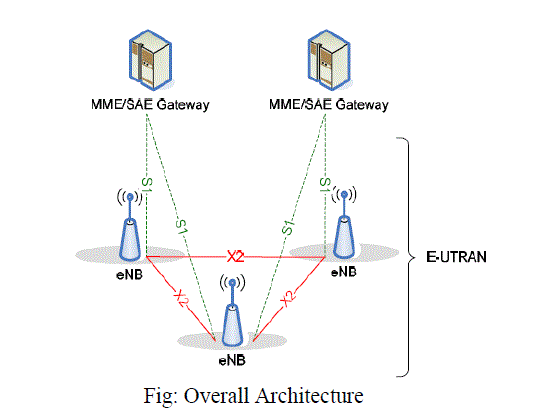
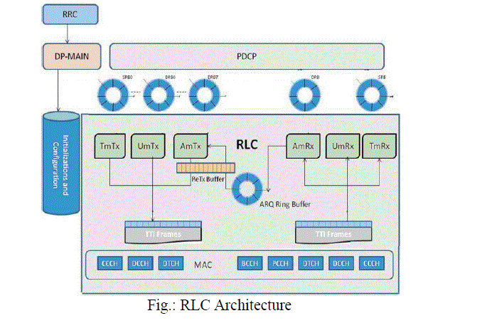
| The E-UTRAN consists of eNBs, providing the E-UTRA user plane and control plane (RRC) protocol terminations towards the UE. The eNBs are interconnected with each other by means of the X2 interface. The eNBs are also connected by means of the S1 interface to the EPC (Evolved Packet Core), more specifically to the MME (Mobility Management Entity) by means of the S1-MME and to the SAE Gateway by means of the S1-U. The S1 interface supports a many-to-many relation between MMEs / SAE Gateways and eNBs. Features Much of the LTE standard addresses the upgrading of 3G UMTS to what will eventually be 4G mobile communications technology. A large amount of the work is aimed at simplifying the architecture of the system, as it transits from the existing UMTS circuit and packet switching combined network, to an all-IP flat architecture system. E-UTRA is the air interface of LTE. Its main features are: ïÃâ÷ Peak download rates up to 299.6 Mbit/s and upload rates up to 75.4 Mbit/s depending on the user equipment category (with 4x4 antennas using 20 MHz of spectrum). Five different terminal classes have been defined from a voice centric class up to a high end terminal that supports the peak data rates. All terminals will be able to process 20 MHz bandwidth. ïÃâ÷ Low data transfer latencies (sub-5 ms latency for small IP packets in optimal conditions), lower latencies for handover and connection setup time than with previous radio access technologies. ïÃâ÷ Improved support for mobility, exemplified by support for terminals moving at up to 350 km/h (220 mph) or 500 km/h (310 mph) depending on the frequency band OFDMA for the downlink, SC-FDMA for the uplink to conserve power ïÃâ÷ Support for both FDD and TDD communication systems as well as half-duplex FDD with the same radio access technology ïÃâ÷ Support for all frequency bands currently used by IMT systems by ITU-R. ïÃâ÷ Increased spectrum flexibility: 1.4 MHz, 3 MHz, 5 MHz, 10 MHz, 15 MHz and 20 MHz wide cells are standardized. (W-CDMA requires 5 MHz slices, leading to some problems with roll-outs of the technology in countries where 5 MHz is a commonly allocated amount of spectrum, and is frequently already in use with legacy standards such as 2G GSM and cdmaOne.) ïÃâ÷ Support for cell sizes from tens of metres radius (femto and picocells) up to 100 km (62 miles) radius macrocells. In the lower frequency bands to be used in rural areas, 5 km (3.1 miles) is the optimal cell size, 30 km (19 miles) having reasonable performance, and up to 100 km cell sizes supported with acceptable performance. In city and urban areas, higher frequency bands (such as 2.6 GHz in EU) are used to support high speed mobile broadband. In this case, cell sizes may be 1 km (0.62 miles) or even less. ïÃâ÷ Supports at least 200 active data clients in every 5 MHz cell. ïÃâ÷ Simplified architecture: The network side of E-UTRAN is composed only of eNode Bs ïÃâ÷ Support for inter-operation and co-existence with legacy standards (e.g. GSM/EDGE, UMTS and CDMA2000). Users can start a call or transfer of data in an area using an LTE standard, and, should coverage be unavailable, continue the operation without any action on their part using GSM/GPRS or W-CDMA-based UMTS or even 3GPP2 networks such as cdmaOne or CDMA2000) ïÃâ÷ Packet switched radio interface. ïÃâ÷ Support for MBSFN (Multicast-Broadcast Single Frequency Network). This feature can deliver services such as Mobile TV using the LTE infrastructure, and is a competitor for DVB-H-based TV broadcast. The figure below depicts the RLC implementation architecture details. RRC layer in the CP receives the configuration information from the eNodeB and passes this information to DP-Main task through interface messages, which then configures RLC for all the parameters corresponding to the RLC mode of the respective Signaling/Data radio bearer. RLC manages different RLC entities pertaining to different RLC modes TM ,UM and AM both in Tx and Rx paths which are initializes during the radio bearer creation. |
 |
| Interfaces DCP RLC communication is through Ring Buffers. In Transmission Side there are 11 Ring Buffers(SRB0,SRB1,SRB2,DRB0-7).PDCP writes the data to Ring Buffers using write Index and RLC reads the data from Ring Buffers using read index. RLC and MAC are closely coupled in a single thread in Tx and Rx Path. In Tx path MAC invokes RLC module with MAC-Opportunity for each logical channel. RLC services the MAC Opportunity by picking PDCP data packets from the ring buffer and packing them into TTI frame of respective logical channel. In the Rx path MAC invokes RLC module with the TTI frame with the received RX data, RLC module processes this data and places PDCP data packets into the RLC_PDCP ring buffer interface. |
IV. EXPERIMENTAL RESULTS |
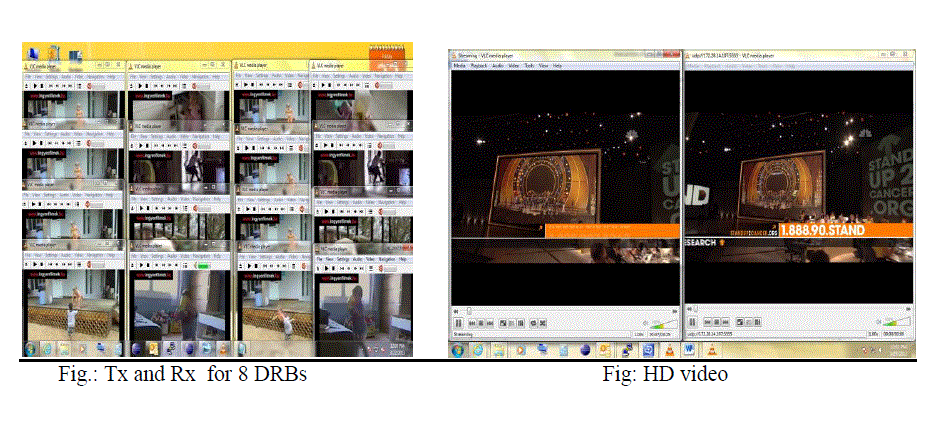
| Tx and Rx using 8 DRBs Here 8 DRBs are been used for data transfer. In earlier releases the use of only 1 DRB was possible for data transfer. One Tx and Rx player is used to represent the data transformation done by each DRB. HD video In the previous versions only the SD video streaming was possible. Now we have upgraded it to support the streaming of HD video. |
 |
V. CONCLUSION |
| The 4G LTE technology is nothing less than ground breaking. The advancements that have been made from 3G to 4G LTE alone are mind blowing. With the data processing speed being increased to at least 1000 Mbit/sec the possibilities are limitless in the wireless communication world. Everything with this new technology has been brought to a new standard. The security, with the complete IP-based solutions allows the user to use the full capability of the phone as well as feel completely secure at the same time this is one of the most vital aspects that has been upgraded from the previous wireless communication technologies. Even though the hardware and coverage areas aren’t up to par yet though, isn’t that big of a setback. The technology is still considered brand new and will only be improved in the coming years. |
References |
|