Keywords
|
| GSM Modem, Potentiometer, Analog to Digital Converter |
INTRODUCTION
|
| Human’s day to day life is now running under commercial vehicles. Without those Vehicles, people have no tasks in the world. There is no house without any petroleum vehicles nowadays. With the rapid increase in traffic, car following has become the most frequent driving scenario. A 2012 report says that there is One four wheeler is available for every three houses. So it is our first duty to make the driver’s or passenger’s safety. A Recent report says that 73.58% of road accidents are happening due to Drunken Driven. Even we have a lot and lots technologies are available, still we are always failing in this type of road accidents. So, now I am going to enhance the below points and let make the solutions for that. Why the previous methods were failed in this field? Why they could not able to control the accidents? What is the status of the Alcohol sensor and Alcohol control unit in the existing system? Where is the placement of the existing unit? Why this is much needed? These are all the points I am willing to enhance in my phases. Main motive of my project is to reduce the Drunken Drive accidents from 73.58% to 0%. |
| A self-learning algorithm or driver characteristics is proposed based on the recursive least square method with a forgetting factor. Using this algorithm, the parameters of the driver model can be identified from the data in the manual operation phase, and the identification result is applied during the automatic control phase in real time. A test bed with an electronic throttle and an electro hydraulic brake actuator is developed for system validation. The experimental results show that the self-learning algorithm is effective and that the system can, to some extent, adapt to individual characteristics. With the development of automation, all the vehicles are coming under luxuries facilities. |
| A. Existing Technologies |
| In recent years, several FCW/CA and ACC algorithms considering driver behavior have been developed. They developed an assistance system with both ACC and FCW functions, which was knowledge, rule, and skill based and was related to driver psychological behaviors. The conceptual, theoretical, and experimental results illustrated how ideas from psychology of human factors, vehicle dynamics, and control technologies could be melded into the design of human-centered driver assistance systems. However, the warning thresholds were fixed and adjusted by the driver. The parameters of driver behavior were identified based on lump sum experimental data, which could not be obtained online. They also proposed an FCW algorithm, which was based on road friction coefficients and driver characteristics. The warning threshold was determined from time to collision. The authors pointed out that the individual driver parameters in a future model would be determined from the analysis of normal driving data. |
| The effectiveness of such a situation-adaptive forward collision avoidance system would be verified by real world driving experiments. They established ACC model with humanlike driving capabilities based on a neural network approach that was intended to assist drivers under safe car-following conditions by providing feasibility indications. The trajectory-based estimation required significant computational time (several minutes), which was not suitable for real-time learning. Although the efforts of improving ADAS performance and acceptability are being carried on by many challenges in adapting to individual driver behavior remain. |
| (i)Developed a self learning algorithm to improving the alcohol sensor unit in vehicles. By this, the resultant only changes in the parameters of driver characteristics. This algorithm could not get changes in full accident control. |
| (ii)They introduced programming and addressing the problem of safety driving in urban areas, where the principal limiting factor is vehicle-to-vehicle or vehicle-to-infrastructure communications. Time-varying networkinduced delays constitute the main concern of networked control systems since they may negatively affect the velocity control of a vehicle at low speeds and consequently cause an accident. A system to adapt the vehicle’s speed to avoid or mitigate possible accidents has been developed. |
| B. Proposed System |
| The weakness of the above systems is their lack of alternative control mechanisms. In our model, mainly concentrated on three controlling strategies which are via |
| • ASU – Alcohol Sensor Unit. |
| • FSU – Forced Sensor Unit & |
| • SCU – Speed Control Unit. |
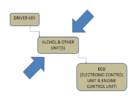
| The truck drivers always use to drive the vehicles for long time. They people usually taking drinks while drive at night time. This leads to big accident problem in the highway roads. This paper ensures that the advancement in Alcohol Sensor unit in the vehicles. The total vehicle control is taking over by this proposed system kit and also this reduces the accidents due to drunken driver problem to 0%. In the existing system, the signal is directly goes from driver key to ECU. But in case of this proposed system, the signal is allowed by the proposed kit. That can said to be as, the proposed system kit is like a ‘checking inspector’ at the check post of roadways. Let see the components used in this proposed system. |
| There is one stand by signal (mobility charge signal) is going to the alcohol sensor unit always. So that it can able to sense always even though the vehicle is in off condition. If the driver enters into car, the Alcohol Sensor control unit senses the inside atmosphere of that vehicle. If the driver consumes some amount of Alcohol means, surely it will intimate in those small inside atmosphere of the vehicle. The Alcohol sensor senses are in three types of categories that are following below. |
| • Maximum Alcohol sensing (not allow to start) |
| • Minimum Alcohol sensing (allows the limited speed) |
| • Nil level (allows to normal vehicle operation) |
| The above three types are programmed under the MPLAB tool that have been embedded into the microcontroller. So that it can able to act like the dependent speed and limits. If it is in first level means, the controller will not send the signal to the Vehicle’s ECU. So there is no more option to drive the vehicle under the 1st Condition. If it is in second level means, the controller will allow to start the engine but in the limited speed. After sending the signal to the ECU, suddenly it sends the signal to the motor as much the limited speed. So, there is no possible to drive the vehicle when the driver is in 2nd condition. |
| If it is in third level means, the controller will allow the ECU to its normal Operation. At the second level, additionally there is one more feature is also available in this proposed system. After allowing the driver to drive the vehicle by limited speed, the controller will sends the text message to the two important mobile numbers that is more related with the vehicle and the driver. |
| So that they may able to pick the person in the respected via. This lead to biggest safety from the road accidents due to the Drunken Drive. At the time of second level, there is possible for the respected person drive the vehicle without touching the steering. This is also leads to the biggest accident problem. So the force sensor does the task by watching the steering condition in the stand by mod e of signal. If the hands are not touch in that steering for more than 3 seconds means, controller will reduce the motor’s limited speed to zero. This is the overview of this proposed system. |
SYSTEM ARCHITECTURE
|
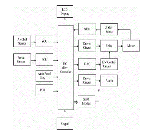
| If it is in first level means, the controller will not send the signal to the Vehicle’s ECU. So there is no more option to drive the vehicle under the 1st Condition. If it is in second level means, the controller will allow to start the engine but in the limited speed. After sending the signal to the ECU, suddenly it sends the signal to the motor as much the limited speed. So, there is no possible to drive the vehicle when the driver is in 2nd condition. If it is in third level means, the controller will allow the ECU to its normal Operation. |
| At the second level, additionally there is one more feature is also available in this proposed system. After allowing the driver to drive the vehicle by limited speed, the controller will sends the text message to the two important mobile numbers that is more related with the vehicle and the driver. So that they may able to pick the person in the respected via. This was lead to biggest safety from the road accidents due to the Drunken Drive. |
| A. Microcontroller |
| This unit contains the software components such as the home appliances control system through which the appliances are controlled. Here we used Microchip’s PIC16f877a microcontroller which is having five ports and consisting of 40 pins. Here the microcontroller acts as the central processing unit (i.e.) brain of the system. The microcontroller is able to communicate when there is a need to access the network for sending or receiving data. Since the microcontroller is an electronic device, the signals that enter it must be electrical. In order to make an electrical or mechanical machine communicate with the microcontroller an interface has to be used. The microcontroller takes the data from the interface and makes some calculations if needed then translates the data into some commands so the module can understand it. The controller also takes the data from the module then translates the data to the interface to control the machine. The number of monitored systems does not depend on the number of inputs that the microcontroller has. For instance, if the microcontroller has five inputs then it can monitor more than five parts of the vehicle. |
| B. Global system for mobile communication (GSM) |
| The Global System for Mobile Communications (GSM) is the most popular standard for mobile phones in the world. The key advantage of GSM systems has been higher digital voice quality and low cost alternatives to making calls such as text messaging. The advantage for network operators has been the ability to deploy equipment from different vendors because the open standard allows easy inter-operability. The GSM is an excellent choice in establishing a communication from remote locations where Internet may not be available. The communication between the user and the home is established by the SMS (Short Message Service) protocol. A GSM modem is connected to the home automation server. The communication between the home automation server and the GSM modem is carried out by the AT (Attention) commands. |
| C. Short message services (SMS) |
| A convenient facility of the GSM network is the short message service. A message consisting of a maximum of 160 alphanumeric characters can be sent to or from a mobile station. This service can be viewed as an advanced form of alphanumeric paging with a number of advantages. If the subscriber's mobile unit is powered off or has left the coverage area, the message is stored and offered back to the subscriber when the mobile is powered on or has reentered the coverage area of the network. This function ensures that the message will be received. |
| D. Alcohol Sensor Unit |
| Ideal sensor for use to detect the presence of a dangerous Alcohol in your car or in a service station, storage tank environment. This unit can be easily incorporated into an alarm unit, to sound an alarm or give a visual indication of the Alcohol concentration. The sensor has excellent sensitivity combined with a quick response time. |
| E. Flux/Force Sensor |
| A force-sensing resistor is a material whose resistance changes when a force or pressure is applied. They are also known as "force-sensitive resistor" and are sometimes referred to by the initialize "FSR".[1] Note that FSR and "Force Sensing Resistor" are trademarks of Interlink Electronics, Inc. Force-sensing resistors consist of a conductive polymer, which changes resistance in a predictable manner following application of force to its surface. They are normally supplied as a polymer sheet or ink that can be applied by screen printing. The sensing film consists of both electrically conducting and non-conducting particles suspended in matrix. The particles are sub-micrometer sizes, and are formulated to reduce the temperature dependence, improve mechanical properties and increase surface durability. |
| Applying a force to the surface of the sensing film causes particles to touch the conducting electrodes, changing the resistance of the film. As with all resistive based sensors, force-sensing resistors require a relatively simple interface and can operate satisfactorily in moderately hostile environments. Compared to other force sensors, the advantages of FSRs are their size (thickness typically less than 0.5 mm), low cost and good shock resistance. However, FSRs will be damaged if pressure is applied for a longer time period (hours). A disadvantage is their low precision: measurement results may differ 10% and more. |
| F. IR Speed Sensor |
| This circuit is designed to monitor the speed of the motor. The holes type pulley is attached in the motor shaft. The pulley is rotated across the USLOT. The USLOT consists of IR transmitter and receiver. Infrared transmitter is one type of LED which emits infrared rays generally called as IR Transmitter. Similarly IR Receiver is used to receive theIR rays transmitted by the IR transmitter. One important point is both IR transmitter and receiver should be placed straight line to each other. |
SYSTEM IMPLEMENTATION
|
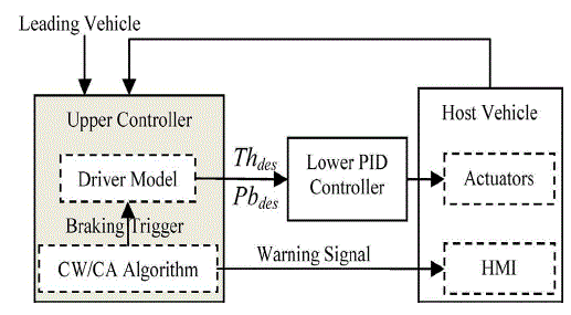
| The overall structure of the control strategy for the ADAS is shown in Fig. 3. The upper controller imitates the driver’s operation and comprises two parts: 1) a driver model for desired control variable generation and 2) an FCW/FCA algorithm for system warning and automatic braking activation. The inputs of the upper controller are the motion states of the leading vehicle and the host vehicle, and the outputs include the desired throttle depression, desired brake pressure and warning signal. The lower controller makes the actuators follow the desired control variables with a proportion–integral–differential control algorithm. The human–machine interface (HMI) sends acoustic and visual warning signals to the driver. |
RESULTS
|
| The Results of the respective paper was taken over by the Proteus tool and the Outputs are shown below in Fig 5. Speed of the vehicle is considered as Variable voltage in this tool. Hence depending upon the variable voltage, respective output can be changed. The domain of the paper has been achieved by help of this tool. |
| The above Figure 5a shows the Initial State of the tool (Engine). Fig 5b shows the starting state of the Engine. Here we want to raise the speed by rising up the variable voltage. Here we can see the changes as an initial state. Fig 5c ensures the set point values of Alcohol Sensor, Speed limits. These are the important parameters to the rapid change of respected output. Fig 5d shows that the Engine is in Full Speed at the instant. We can see the result due to the speed change in the newt figure shown. |
CONCLUSION
|
| By this paper, we had seen about the Alcohol Sensor unit in vehicles and the advancement. Surely it will reduce the road accidents due to Drunken Driver to 0%. The driver tests in real traffic have been conducted, which provide a database for driver behavior analysis and adaptive ADAS design. Based on the analysis of steady car following, THW of the driver distribute in a relatively concentrated area. |
| This indicated that these two parameters can be considered as the driver control targets. A linear relationship between the driver operation and vehicle states has been adopted to establish a driver model to imitate driver operations in different modes and the transition in between. With the RLS method, the self-learning ACC and FCW/FCA algorithms for driver characteristics have been proposed to identify the model parameters online from a data sequence of manual operation, which are then used in automatic driving mode. |
| |
Figures at a glance
|
 |
 |
 |
 |
| Figure 1 |
Figure 2 |
Figure 3 |
Figure 4 |
|
 |
 |
 |
 |
| Figure 5a |
Figure 5b |
Figure 5c |
Figure 5d |
|
| |
References
|
- S.Tsugawa, “Trends and issues in safe driver assistance systems,” IATSS Res., vol.30, no.2, pp.6–18, 2006.
- W.Prestl, “The BMW active cruise control ACC,” Soc. Auto mob Eng., Washington, DC, SAE, 2000.
- Y.Umemura, “Driver behavior and active safety (Overview),” Toyota CRDL, vol.39, no.2, pp. 1–8, 2004.
- K.Yi and J.Chung, “Nonlinear brake control for vehicle CW/CA systems,” IEEE/ASME Trans. vol.6, no.1, pp.17–25, 2001.
- Y.Yamamura, T.Murakami, “Development of an adaptive cruise control system with stop-and-go capability,” Soc. Auto mob Eng., Washington, DC, SAE, 2001.
- G.A.Bekey and G.O.Burnham, “Control theoretic models of human drivers in car-following,” Human Factors, vol.19, no.4, pp.399–413, 1977.
- F.Ray, “A conceptualization of driving behavior as threat avoidance,” Ergonomics, vol.27, no.11, pp.1139–1155, Nov. 1984.
- P.Fancher, F.Bareket, and R.Ervin, “Human-centered design of an ACC with braking and forward-crash-warning system,” Veh. Syst. Dyn., vol.36, no.2/3, pp.203–224, 2001.
- M.Nakaoka and M.Nagai, “Study on forward collision warning system adapted to driver characteristics and road environment,” in Control, Auto mob Syst., 2008.
- F.Simonelli and V.Martinis, “adaptive cruise control systems through a learning machine approach,” Appl Soft, vol.52, pp.240–249, 2009.
|