INTRODUCTION
|
| Distribution systems are the networks that transport the electrical energy from bulk substation to many services or loads. Distribution systems are becoming large and stretched too far leading to higher system losses and poor voltage regulation. Hence there is a need to reduce the system losses. By minimizing the losses, the system may acquire longer life span and has greater reliability. |
| Due to high concentration of inductive loads in distribution system, power and energy losses are more. Shunt capacitors are widely used in distribution system consuming negative VAR, which counteracts some of the lagging components of inductive VAR at the point of installation. Thus, it modifies the characteristics of inductive load. Shunt capacitor results in to a number of benefits like improvement of power factor, reduction of power loss, improvement of voltage profile, improvement of voltage stability and system-released capacity. To achieve these benefits to the utmost extent under various operating constraints, distribution engineers are required to determine the optimal locations, types and sizes of capacitors to be placed and control settings of switched capacitors at different load levels. |
| A variety of solution techniques have been employed to solve the capacitor placement problem. These techniques are classified into four categories. They are analytical methods, numerical programming methods, heuristic search methods and artificial intelligence (AI) based methods. When a realistic problem formulation with all considerations is to be solved, however, most analytical, numerical programming heuristic are unable to work well. In recent years, AI- based methods such as genetic algorithms (GA) have been applied to the capacitor placement problem with promising results. Mean while, some new AI-based methods are introduced and developed. Although these AI- based methods do not always guarantee the globally optimal solution, they will provide sub optimal (near globally optimal) solutions in a short CPU time. |
| A modern AI-based method, particle swarm optimization is used to solve the capacitor placement with all the realistic problem formulation considerations. This optimization technique can be used to solve many of the same kinds of problems as GA, and does not suffer from some of GA’s difficulties. PSO has been found to be robust in solving problems featuring non-linearity, non-differentiability and high dimensionality. |
MATHEMATICAL FORMULATION
|
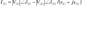
| In any radial distribution system, the electrical equivalent of a branch-1, which is connected between node 1 and 2 having a resistance r(1) and inductive reactance x(1) is shown in figure 1 |
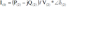
| Current flowing branch-1is given by |
 (1) (1) |
 (2) (2) |
| Where, V(1)(1),V (2) (2) are the voltage magnitudes and corresponding phase angles at sending end node 1 and receiving end node 2 respectively. In general |
 (3) (3) |
| Where, node no., i=1,2,…,nd |
| branch no., j=1,2…,nd-1 |
| nd=total no. of nodes |
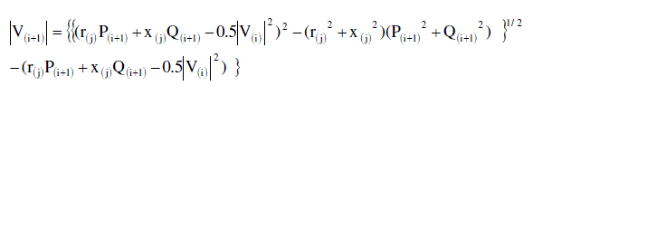
The active and reactive power losses in branch ‘j’ are given by,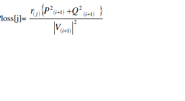 (4) (4) |
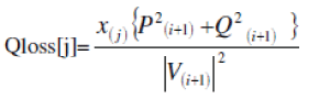 (5) (5) |
| The total active and reactive power losses of the system are |
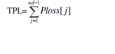 (6) (6) |
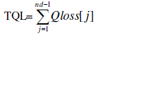 (7) (7) |
| Where |
| Ploss[j], Qloss[j] =Active and reactive power losses of branch ‘j’ |
| TPL, TQL = Total active and reactive power losses of the system |
| Usually the substation voltage V(i) is known and is taken as |V(1)| =1.0 p.u. Initially, Ploss [j] and Qloss [j] are set to zero for all j. Then the initial estimate of P(2) and Q(2) will be the sum of the load of all the nodes beyond node 2 plus the local load of node 2. For all the branches j=1,2…nd-1, compute P(i+1) and Q(i+1) using the algorithm. Compute |V(i+1)|, Ploss(j) and Qloss(j) using equations (2),(4) and (5). This will complete iteration. Update the loads P(i+1) and Q(i+1) (including losses) and repeat the same procedure until the voltage magnitudes are computed to a tolerance of 0.0001 p.u. in successive iteration. |
ALGORITHM FOR NODE IDENTIFICATION
|
| Following algorithm explains the methodology to identify the candidate nodes, which are more suitable for capacitor placement. |
| • Read radial distribution system data. |
| • Run the load flows and calculate the base case active power loss. |
| • By compensating the reactive power injections (Qc) at each node and run the load flows, to calculate the active power losses in each case. |
| • Calculate the power loss reduction and power loss index(PLI). |
| • Select the candidate node whose PLI>Tolerance. |
| • Stop. |
| The proposed algorithm is tested on 15-node radial distribution system, 33-node radial distribution system and 69-node radial distribution system |
| The capacitor sizes at the nodes are obtained from Particle Swarm Optimization. These capacitors are kept at candidate nodes and the load flow solution is performed to observe the improvement in voltage profile and net savings in three systems. |
PARTICLE SWARM OPTIMIZATION
|
| Particle Swarm Optimization (PSO) is a meta heuristic parallel search technique used for optimization of continues non linear problems. The method was discovered through simulation of a simplified social model. PSO has roots in two main component methodologies perhaps more obvious are ties to artificial life in general, and to bird flocking, fish schooling and swarming theory in particular. It is also related, however to evolutionary computation and has ties to both genetic algorithms and evolutionary programming. It requires only primitive mathematical operators, and is computationally inexpensive in terms of both memory requirements and speed. It conducts searches using a population of particles corresponding to individuals. Each particle represents a Candidate solution to the capacitor sizing problem. In a PSO system, particles change their positions by flying around a multi dimensional search space until a relatively unchanged position has been encountered, or until computational limits are exceeded. In social science context, a PSO system combines a social and cognition models. |
| The general elements of the PSO are briefly explained as follows: |
| Particle X(t): It is a k-dimensional real valued vector which represents the candidate solution. For an ith particle at a time t, the particle is described as Xi(t)={Xi,1(t), Xi,2(t),… Xi,k(t)}. |
| Population: It is a set of ‘n’ number of particles at a time t described as {X1(t), X2(t)… Xn(t)}. |
| Swarm: It is an apparently disorganized population of moving particles that tend to cluster together while each particle seems to be moving in random direction. |
| Particle Velocity V(t): It is the velocity of the moving particle represented by a k-dimensional real valued vector Vi(t)= {vi,1(t), vi,2(t)…… vi,k(t)}. |
| Inertia weight W(t): It is a control parameter that is used to control the impact of the previous velocity on the current velocity. |
| Particle Best (pbest): Conceptually pbest resembles autobiographical memory, as each particle remembers its own experience. When a particle moves through the search space, it compares its fitness value at the current position to the best value it has ever attained at any time up to the current time. The best position that is associated with the best fitness arrived so far is termed as individual best or Particle best. For each Particle in the swarm its pbest can be determined and updated during the search. |
| Global Best (gbest): It is the best position among all the individual pbest of the particles achieved so far. |
| Velocity Updation: Using the global best and individual best, the ith particle velocity in kth dimension is updated according to the following equation. |
| V[i][j]=K*(w*v[i][j]+c1*rand1*(pbestX[i][j]-X[i][j])+c2*rand2*(gbestX[j]-X[i][j])). |
| where, K constriction factor c1, c2 weight factors |
| w Inertia weight parameter |
| i particle number, j control variable |
| rand1, rand2 random numbers between 0 and 1 |
| Stopping criteria: This is the condition to terminate the search process. It can be achieved either of the two following methods: |
| i. The number of the iterations since the last change of the best solution is greater than a pre-specified number. |
| ii.The number of iterations reaches a prespecified maximum value |
ALGORITHM FOR CAPACITOR PLACEMENT AND SIZING USING PLI & PSO
|
| step1: Run the base case Distribution load flow and determine the active power loss. |
| Step2: Identify the Candidate buses for placement of capacitors using power loss indices. |
| Step3: Generate randomly ‘n’ number of particles, where each particle is represented as particle[i]={Qc 1,Qc 2,….,Qc j} |
| Where ‘j’ represents number of candidate buses. |
| Step4: Generate the particle velocities (v[i]) between –vmax and vmax. |
| Where, vmax = (capmax-capmin)/N |
| Capmax= maximum capacitor rating in kvar |
| Capmin= minimum capacitor rating in kvar |
| N= number of steps to move the particle from one position to the other. |
| Step5: Set the Iteration count, iter=1. |
| Step6: Run the load flows by placing a particle ‘i’ at the candidate bus for reactive power compensation and store the active power loss (pl). |
| Step7: Evaluate the fitness value (base power loss-pl) of the particle ‘i’ and compare with previous particle best (pbest) value. If the current fitness value is greater than its pbest value, then assign the pbest value to the current value. |
| Step8: Determine the current global best(gbest) maximum value among the particles individual best (pbest) values. |
| Step9: Compare the global position with the previous global position. If the current global position is greater than the previous, then set the global position to the current global position. |
| Step10: Update the velocities by using |
| v[i][j]=K*(w*v[i][j]+c1*rand1*(pbestparticle[i] |
| Where, particle[i] position of individual ‘I |
| gbestparticle best position among the swarm |
| v[i] velocity if individual ‘i’ |
| Step11: If the velocity v[i][j] violates its limits |
| (-vmax, vmax), set it at its proper limits |
| Step12: Update the position of the particle by adding the velocity (v[i][j]) to it. |
| Step13: Now run the load flow and determine the active power loss (pl) with the updated particle. |
| Step14: Repeat step 7 to step 9 |
| Step15: Repeat the same procedure for each particle from steps from 6 to 13. |
| Step16: Repeat steps from 6 to 13 until the termination criteria are achieved. |
RESULTS AND ANALYSIS
|
| Balanced Radial Distribution Systems |
| Example 1: The proposed algorithm is tested on 15-node radial distribution system whose single line diagram is shown in fig 1. The test results are given in Table1. The voltage profile before and after compensation are shown in Fig 2. From the results, to observe that active power losses reduce from 60.34821 kW to 29.77601kW i.e., 50.6596 % loss reduction and minimum voltage improved from 0.942389 p.u to 0.967561 p.u. thus voltage regulation improved from 5.7611% to 3.2439%, i.e., 43.6930 % improved. |
| Example 2: The test results of 33-node radial distribution system are given in Table2.The voltage profile before and after compensation are shown in fig 3. From the results, to observe that active powerlosses reduce from 202.7069 kW to 143.7255 kW i.e., 29.096866% loss reduction and minimum voltage improved from 0.913041 p.u to 0.925082 p.u. thus voltage regulation improved from 8.6959% to 7.4918% i.e., 13.8468 % improved. |
| UNBALANCED RADIAL DISTRIBUTION SYSTEMS |
| Example 1 The proposed algorithm for unbalanced radial distribution system is also tested on unbalanced 19- node radial distribution system. The test results of 19-node radial distribution system are given in Table 4. From the results, it is observed that total active power losses reduce from 13.471 kW to 11.013 kW i.e., 18.27 % loss reduction and minimum voltage of phase A, phase B and phase C improved from 0.951592, 0.949758, 0.950466 p.u to 0.958514, 0.95719, 0.957709 p.u. respectively. |
| Example2: The proposed algorithm for radial distribution system is tested on unbalanced 52-node radial distribution system. The test results of unbalanced 52-node radial distribution system are given in Table 5. From the results, it is observed that active power losses reduce from 159.0603 kW to 131.083 kW i.e., 17.58 % loss reduction and minimum voltage of phase A, phase B and phase C improved from 0.92777, 0.95127, 0.91318 p.u to 0.93783, 0.96002, 0.92386 p.u. |
CONCLUSION
|
| A new approach based on PSO algorithm for solving the shunt-capacitor placement problem in radial distribution systems has been proposed in the project. With full considerations of different load levels, and practical aspects of fixed or switched capacitor banks, the target problem is reformulated by a comprehensive objective function and a set of equality and inequality constraints. The proposed solution method employs PSO to search for optimal locations and sizes of capacitors to be placed and optimal numbers of switched capacitor banks at different load levels. |
| An effective approach for optimum location of capacitor in radial distribution system has been proposed. From the results, several important observations can be concluded as follows. |
| • The power losses of radial distribution system can be efficiently reduced by proper placement of shuntcapacitor. |
| • In addition of power facto |
Tables at a glance
|
 |
|
|
|
|
| Table 1 |
Table 2 |
Table 3 |
Table 4 |
Table 5 |
|
| |
Figures at a glance
|
 |
 |
 |
| Figure 1 |
Figure 2 |
Figure 3 |
|
| |
References
|
- B.Scott and O.Alsac, “Fast decoupled load flow “, IEEE Trans.on Power Apparatus and System Vol. PAS-93, 1974, pp.859-869.
- S.I.Wamoto and Y.Tamura,” A load flow method calculation for ill-conditioned power system, IEEE Trans.on Power Apparatus and System, Vol. PAS-100, 1981, pp.1736-1740.
- D.Rajicic and Y.Tamura,” A modified fast decoupled power flow for network with high R/X ratio”, IEEE Trans.on Power Apparatus and System, Vol. 3, Nov,.1988, pp.341-348.
- W.H.Kresting and D.L.Mendive”, An application of ladder networks theory to the solution of three phase radial load flow problem”, IEEE PES winter meeting, New York, January 1976, paper A76 044-8.
- D.Shirmohammadi and H.W.Hong,” A compensation based power flow method for weakly meshed distribution and transmission networks,” IEEE Trans.on Power Delivery, Vol. 3, Nov,.1988, pp. 753-762.
- M.E.Baran and F.F.Wu,”Optimal capacitor placement on distribution systems” IEEE Trans.on Power Delivery, Vol. 4, January 1989, pp. 725-734.
- James Kennedy, RusselEbehart,” Particle Swarm Optimization” in Proc.Int.Conf, Neural Networks, Vol 4.
- J.Kennedy,”The particle Swarm: Social adoption of knowledge” IEEE, 1997. James Kennedy,”Small words and mega minds, Effects of neighborhood trpology on particle swarm performance”, IEEE 1999.
- D.Thukaram, H.M.Wijekoon Banda and Jovitha Jerome,” A robust three phase power flow algorithm for radial distribution systems” Electric Power Systems Research, November 1
|